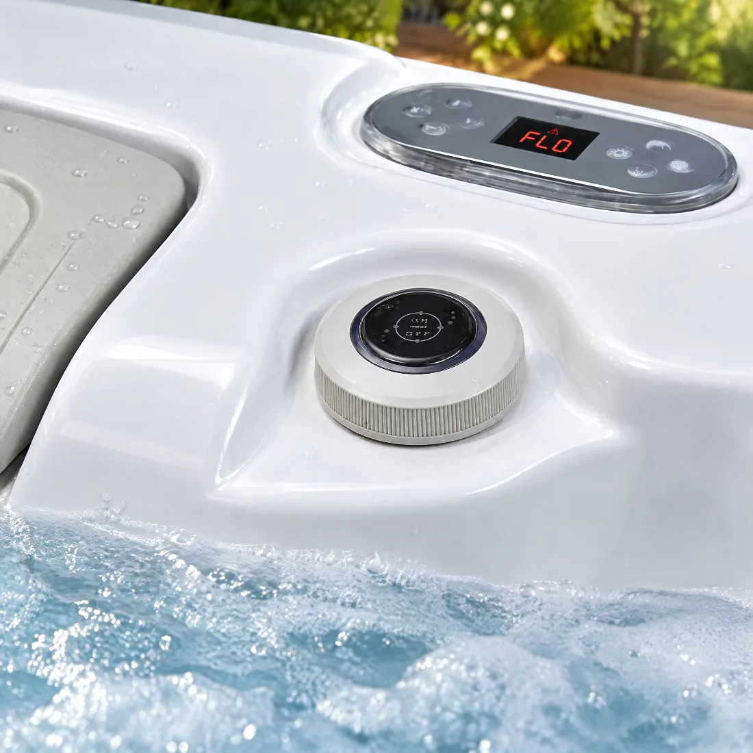
Stepping out to your patio expecting a soothing soak only to find flashing error digits on the topside control screen is an exasperating experience. Encountering a flo error on hot tub displays signals that the internal safety monitors have halted the heating element because water is not circulating across the heating tube at the required rate. Understanding why this protection mechanism activates allows you to isolate the fault quickly, safeguard expensive plumbing components from heat damage, and restore your spa to balanced operation.
Water serves both as the therapeutic medium and as the essential coolant for your spa pack. When fluid velocity drops below a calibrated threshold, internal thermal sensors trigger an automated safety shutdown. Left unchecked, a lack of circulation can scorch the heating element, warp surrounding ABS union connections, or ruin pump seals. Let us explore the mechanical anatomy of this alert, walk through structured diagnostic steps, and examine how proper maintenance prevents future disruptions.
Modern hot tubs rely on automated sensors to verify that adequate water volume passes through the heater manifold before energizing the electric heating coil. Depending on the brand and model, spa packs generally employ a mechanical paddle flow switch mounted in the plumbing line, a pressure switch threaded into the heater housing, or electronic temperature differential sensors built into the heater tube. These safety components act as an electrical gatekeeper.
When the circulation pump or two-speed jet pump engages, the resulting fluid kinetic pressure moves the paddle switch or expands the internal diaphragm of the pressure sensor. This physical movement alters an electrical contact, confirming to the main circuit board that water is moving. If the control board does not receive this confirmation within its programmed detection interval, it cuts power to the heater element and displays a flow warning. Because sensor configurations, operating voltages, and polling delays vary by manufacturer, consult your specific spa manual to identify how your system monitors flow.
Topside digital panels communicate diagnostic data through diverse messaging protocols that depend on the control pack firmware. On some systems, an alert labeled FLO, FL, or FLOW flashes to indicate an open circuit when the pump is commanded to run, while a solid readout can denote a switch that fails to open when the pump stops. Other systems report numeric codes such as FL1 or FL2, or alternative designations like FLC, to differentiate between open circuits and closed switch states.
Because code behaviors and display abbreviations differ significantly across controller brands, you should never assume a universal meaning for solid versus flashing alerts. Always consult the troubleshooting section of your spa or control pack manual to verify the precise condition indicated by the specific characters on your screen before deciding on a repair path.
Entering a spa that exhibits an active flow error is strongly discouraged. Many control systems deactivate the heater upon detecting low flow, which allows the water temperature to steadily drop toward ambient conditions. Soaking in cooling water defeats the primary purpose of hydrotherapy, but equipment protection and water sanitation considerations also take precedence.
Without adequate circulation, sanitizing chemicals such as dissolved chlorine or ozone cannot disperse evenly throughout the vessel, leaving stagnant pockets where bacterial contamination can develop. Furthermore, if an erratic flow sensor fluctuates or underlying electrical faults exist, heating behavior can become unpredictable. Turning off the equipment and resolving the alert before further use remains the safest course of action.
The most frequent culprit behind an unexpected flo error on hot tub installations is a severely choked cartridge filter. Spa filters are engineered to trap suspended solids, dead skin cells, cosmetic oils, and microscopic debris. Over weeks of daily use, these trapped particles form an impermeable barrier across the pleats, drastically reducing total fluid volume passing into the intake line.
Even when a filter fabric appears visually clean, calcium carbonate crystallization and invisible body oil residues can coat the synthetic fibers. This unseen glazing chokes water intake, starving the primary wet end of the pump. The pump impeller continues spinning, but without an adequate fluid volume supplied through the filter core, hydraulic line pressure collapses below the sensor threshold.
Centrifugal spa pumps require an adequate water head to operate effectively because they cannot compress air. If natural evaporation, heavy bather splash-out, or an unresolved slow leak allows the water level to drop below the manufacturer’s recommended operating level, atmospheric air can be drawn into the plumbing intake.
Depending on skimmer design and water depth, air entering the suction line can disrupt pump priming and reduce total circulation. When aerated water passes through the wet end, hydraulic line pressure can drop below the threshold required by the flow sensor, leading to an active error message.
Air locks represent an acute mechanical hurdle that routinely occurs immediately following a complete water change. When a hot tub is refilled by dropping an ordinary garden hose directly into the open footwell, water rises from the bottom upward, sealing off internal plumbing lines before air can escape through the small jet orifices.
This entrapped atmospheric volume creates a dense air pocket inside the pump volute and upper heater manifold. Because the pump impeller spins inside a trapped air bubble, it cannot establish suction or prime itself against the water column. The topside display will cycle through its startup diagnostics, engage the pump, register zero dynamic water movement, and trigger an immediate flow malfunction code.
Physical restrictions along the suction or discharge lines mechanically choke water throughput. Modern hot tub shells incorporate submerged suction grates in the lower footwell designed to prevent entrapment while supplying water volume. If bathers inadvertently cover these grates with towels, or if autumn leaves accumulate against the intake mesh, suction drops precipitously.
Similarly, internal maintenance gate valves—often called slice valves—can cause silent hydraulic failure. Located on either side of the heater and pump to allow equipment servicing without draining the spa, these valves can vibrate partially shut over time or have their internal plastic gate stems shear off while the external handle remains in an apparently open position.
When external physical factors have been eliminated, internal mechanical wear or electrical component failure must be addressed. Circulation pumps run for extended daily filtration cycles, eventually suffering from motor bearing fatigue, worn run capacitors, or broken impeller vanes that spin loosely on the motor drive shaft.
Flow switches and pressure sensors are also subject to continuous thermal and chemical stress. The flexible plastic paddle inserted into the pipe tee can become brittle from sanitizer exposure and snap off cleanly, leaving the microswitch open regardless of how forcefully water rushes through the line. Alternatively, internal switch contacts can oxidize or corrode, preventing clean electrical signal transmission back to the central circuit board.
Diagnostic procedures on electrical spa equipment must always begin with safety precautions. Before touching any internal equipment, filters, or wet-end fittings, locate the dedicated GFCI breaker panel on the exterior wall near the hot tub installation. Toggle the double-pole switch firmly to the OFF position.
Confirm that the topside display screen goes completely dark and that all pump vibration ceases. Working inside a wet equipment bay while high-voltage circuits remain energized carries a severe risk of electric shock. Never attempt to inspect internal sensors or clear blockages while the electrical supply is connected.
Inspect the physical water line inside the acrylic shell against the manufacturer’s molded level marks or the level specified in the spa owner manual. Maintaining proper water height ensures the skimmer assembly remains submerged and prevents intake vortexing.
If the water level rests below the indicated threshold, introduce fresh water using a standard garden hose to restore the proper fill line. Observe the floating skimmer weir gate as the tub fills. The weir should pivot effortlessly on its hinge pins; a stuck or jammed weir flap acts as a dam, starving the filter well of water.
To determine whether your filter cartridge is choking the hydraulic circuit, review your owner manual to verify whether a brief filter-removal test is permitted. If the manufacturer allows this diagnostic step, ensure power remains disabled, open the skimmer canister or unscrew the threaded retainer, and remove the cartridge.
Check the pleats for calcification, embedded dirt, or heavy bio-film. If running the spa without a filter is authorized, supervise the tub closely for a brief period to ensure no loose debris enters the open suction line. Restore power at the GFCI breaker. If the flo error on hot tub display disappears quickly, the cartridge is exhausted and must be cleaned or replaced. If your manual advises against operating without a filter, proceed directly to thoroughly cleaning or replacing the cartridge before contacting a professional.
When an error persists following a refill and the pump hums without producing actual flow, air trapped in the pump casing is often the cause. Always consult your spa manufacturer’s approved priming and air-bleed instructions before attempting manual adjustments.
Many manufacturers recommend cycling the pump briefly between low and high speeds, or backfilling water through the filter standpipe with a garden hose to push air out through the jets. If manual air bleeding at a plumbing union is specifically described in your manual, follow the exact safety guidelines provided. If no approved consumer procedure is detailed, or if you are unfamiliar with hot tub plumbing, avoid loosening pressurized fittings and contact a qualified technician to prime the system safely.
Examine the lower suction intake fittings situated within the footwell and lower bench contours of the acrylic shell. These specialized suction points incorporate anti-vortex grates secured with stainless steel machine screws designed to distribute negative intake pressure across a broad surface area.
Check whether accumulated silt, organic yard matter, or small spa accessories have drifted across the intake apertures. Reach down and clear away any surface obstructions by hand. Ensure the plastic grates sit securely flush against their mounting bezels without cracks or missing sections that could allow foreign debris into the internal impeller assembly.
Once physical and hydraulic checks have been executed, consult your controller manual to determine how your specific system clears fault codes. Different control packs manage error retention and automated recovery differently, with some clearing codes automatically once flow resumes while others provide a specific button sequence.
If your manual recommends a power-cycle restart, disconnect power at the main GFCI breaker according to the instructions in your manual before restoring electrical supply. Monitor the startup sequence as the digital topside panel initializes. If the error code persists or re-engages after the priming cycle completes, avoid repeated breaker cycles and schedule an inspection with a certified spa professional.
Troubleshooting hydraulic faults requires separating physical blockages from electrical feedback irregularities. Because control panel nomenclature differs across brands, verify these common symptom patterns against your specific equipment manual before taking action.
| Topside Symptom | Physical Water Condition | Probable Underlying Cause | Severity Level | Corrective Action Protocol |
|---|---|---|---|---|
| Flow Alert (Low Flow State) | Low water level; pump audible but surging | Air entering suction line, breaking pump prime | Moderate | Replenish water depth to recommended mark; inspect weir flap. |
| Flow Alert (Restriction State) | Normal water level; jets feel weak or dormant | Severely loaded cartridge filter choking pump intake | Low | Clean or replace cartridge; test per manufacturer guidelines. |
| Solid / Closed-Switch Alert | Pump completely off; tub quiet | Flow switch contacts mechanically stuck closed | High | Inspect switch alignment per manual; replace defective component. |
| Error Code after Refill | Normal water level; pump hums without flow | Air lock trapped inside pump volute casing | Moderate | Follow factory priming procedure; refill via filter standpipe. |
| Intermittent Flow Code | Jets running normally; error appears during heating | Sensor calibration drift, wire corrosion, or line restriction | Moderate | Check wiring connections; refer to manual or arrange service. |
| Flow Alert with Breaker Trip | Water cold; GFCI clicks off immediately | Heater short or grounded pump motor winding | Critical | Discontinue use immediately; summon a certified spa technician. |
When standard cleaning, water leveling, and air purging routines fail to extinguish the flow error, internal electronic faults within the control pack must be addressed. Testing low-voltage communication leads and terminal continuity requires a calibrated digital multimeter and an understanding of printed circuit board schematics.
Corroded Molex connectors, burned traces on the circuit board, or internal microcontroller faults cannot be resolved through routine adjustments. Forcing an out-of-spec pressure switch or bridging sensor terminals to bypass an active error exposes the spa to catastrophic dry-fire risks. Certified technicians carry the proprietary factory diagnostics needed to trace sensor telemetry safely.
If the circulation pump or jet pump produces a loud metallic hum, screeches upon startup, or trips the main GFCI breaker instantly, the internal electromechanical assembly has experienced failure. Electric motors operating in warm, humid spa enclosures face eventual shaft seal degradation.
When water bypasses the ceramic mechanical seal, moisture penetrates the forward motor bearings, causing heavy rust, shaft seizure, and shorted stator windings. Attempting to force a frozen motor shaft to turn can melt the run capacitor or ignite motor insulation. A qualified spa professional should evaluate whether replacing the pump wet end, rebuilding bearings, or swapping the entire motor is required.
Structural plumbing failures nestled beneath dense polyurethane insulation foam require specialized tools to locate and repair. If an internal slice valve stem snaps internally, the gate can drop down into the pipe bore, acting as an invisible guillotine valve that permanently chokes flow despite the external handle appearing normal.
Excavating perimeter foam, cutting PVC pipe manifolds, and solvent-welding pressure fittings in cramped equipment cabinets carries a risk of creating secondary leaks if executed improperly. Certified technicians possess the endoscopic inspection cameras, thermal imaging equipment, and plumbing tools required to resolve concealed hydraulic restrictions without compromising shell framing.
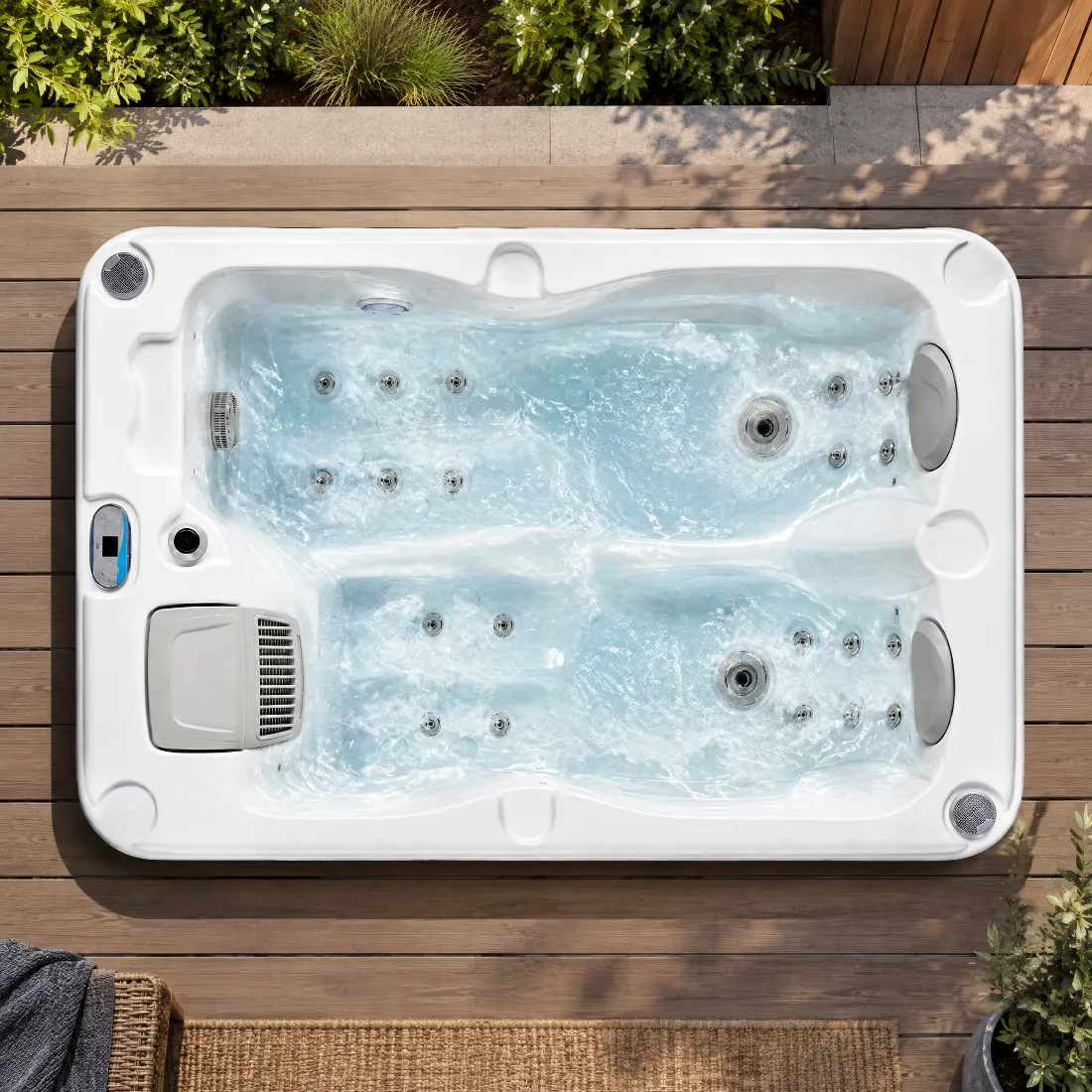
Achieving balanced hydraulic flow requires matching pump power output directly against plumbing line friction and jet nozzle resistance. For us at Ocean Future, systems like the OF-2001 2-Person Hot Tub are built to streamline these fluid dynamics, ensuring reliable circulation across compact domestic hydrotherapy spaces. Measuring 2000 by 1350 by 800 mm with an empty dry weight of 200 kg, this spa layout balances total power consumption against performance demand.
The system utilizes an LX Water Pump rated at 1500W to drive water throughout its manifold network, feeding a coordinated array of 22 precision massage jets. Two larger 5-inch hydrotherapy jets work in tandem with twenty targeted 1-inch jets to provide thorough tension relief across the back and shoulder zones. A matched 2000W LX heater conditions the circulating water, drawing upon a digital control pad to monitor operating parameters and manage system sequencing smoothly.
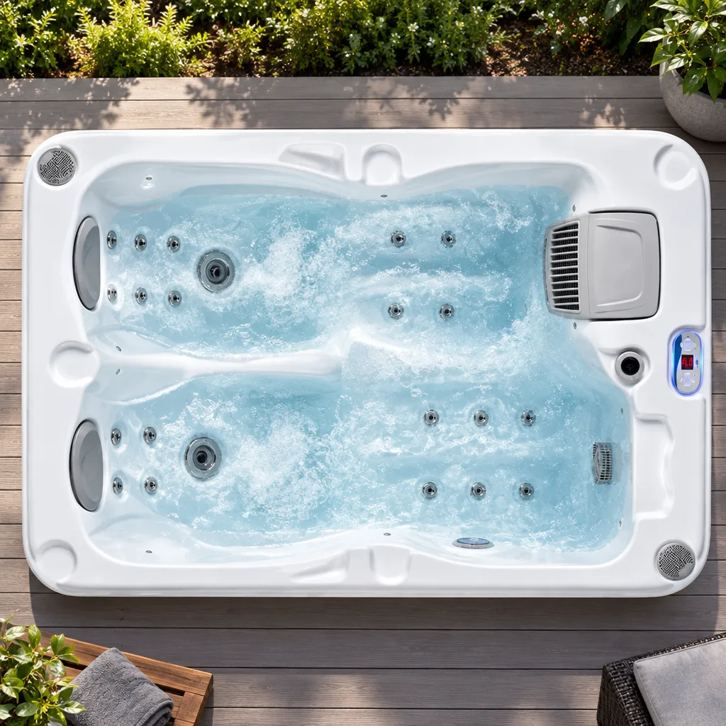
Reliable water circulation depends on keeping filtration and sanitation elements clean and uninhibited. According to the product technical specifications for the OF-2001, the system includes a dedicated filtration setup with a filter cartridge and copper-zinc purification, along with an ozone generator for sanitization support.
The spa specifications also detail an intake and drainage arrangement comprising one water suction fitting and one water drainer set. All components operate within an overall 3500W system specification, pairing the 1500W LX pump, 2000W LX heater, and digital control pad to support circulation and hydrotherapy across the dual recliner positions.
Compact two-person loungers operate within tight fluid capacity tolerances compared to large family-sized spas. In a vessel containing a concentrated water volume, minor evaporation or bather displacement has an amplified effect on total water level relative to the skimmer inlet.
To ensure consistent circulation and protect the glossy UV-resistant American acrylic shell, high-density foam shell insulation, and 15mm PU-insulated aluminum-plastic skirt panels, owners must adhere strictly to specified operational guidelines. Maintaining adequate fill depth ensures that the ozone injector, bottom light, perimeter LEDs, and 1-inch air control switches function in harmony without hydraulic starvation.
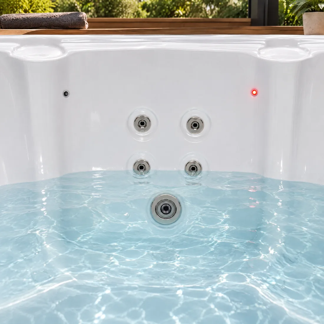
Preventing unexpected flow halts requires moving from reactive troubleshooting to structured, preventative cartridge care. Filter pleats act as micro-sieves that experience progressive loading over time. Implementing a consistent cleaning cadence according to your owner manual preserves hydraulic flow rates across all seasons.
The physical technique applied when refilling your spa can influence whether air becomes trapped in the plumbing. When preparing to refill the vessel, always consult your specific model instructions for the recommended filling point.
If your spa manual instructs you to insert the garden hose directly into the filter well or standpipe, following this method allows water to enter the internal plumbing and pump lines first. As water fills the lower manifold and rises within the shell, it helps push atmospheric air outward through the jet nozzles. While this technique does not guarantee total airlock prevention, it significantly reduces the likelihood of air pockets forming around the pump impeller.
Water chemistry balance extends beyond basic sanitation; it directly dictates the mechanical longevity of internal sensors. Unbalanced water that trends excessively alkaline drives dissolved calcium out of solution, depositing hard mineral scale across the heater sheath and moving parts of flow switches.
Always follow your spa manufacturer’s water-care instructions regarding pH, sanitizer concentration, and total alkalinity targets. Keeping water balanced prevents aggressive corrosion of metallic heater components and inhibits mineral scale accretion on sensor probes, ensuring your topside control pad continues reading accurate flow dynamics year after year.
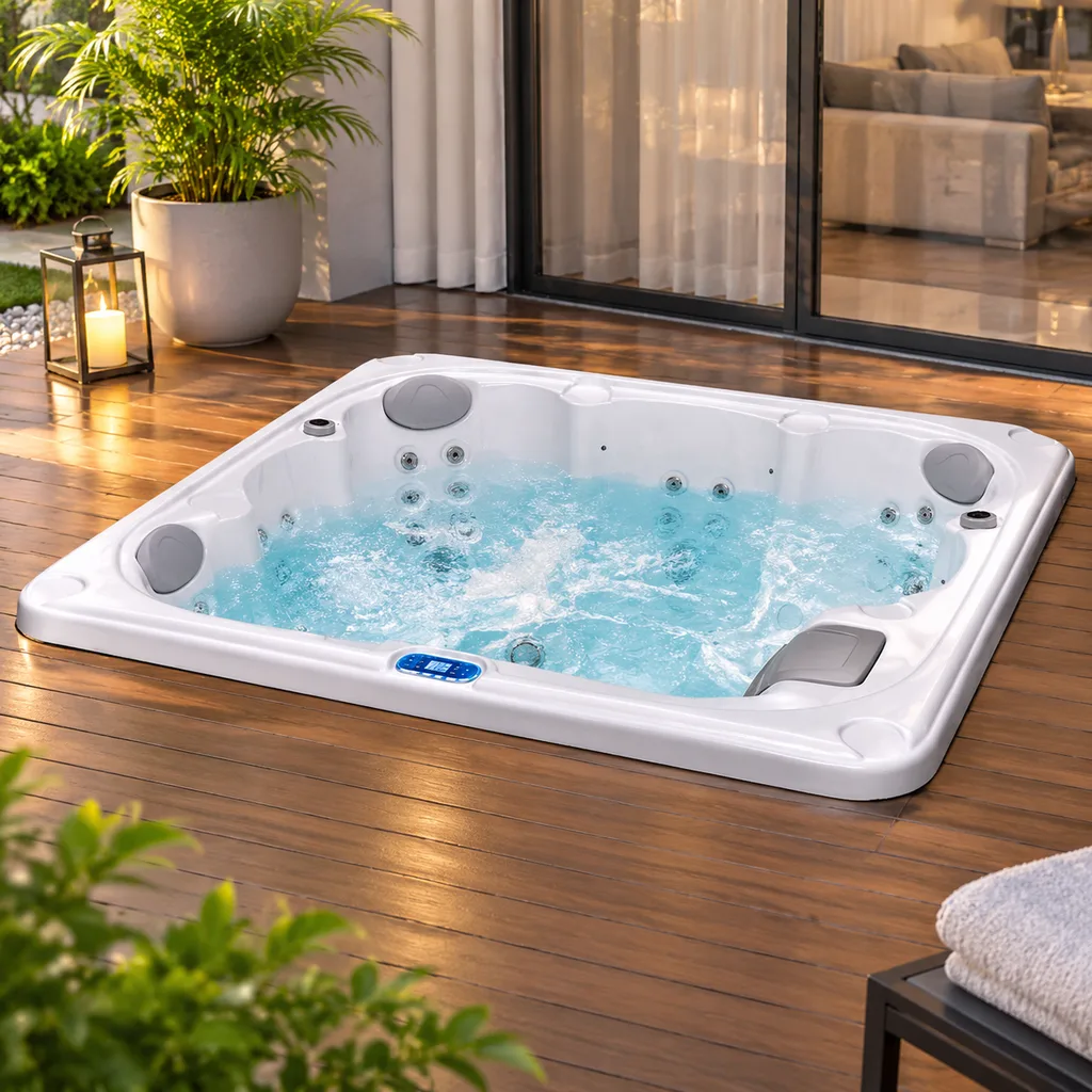
A new filter cartridge can occasionally trigger a flow code if it is not installed properly or if air becomes trapped within the housing during installation. Inspect the cartridge to verify it is seated squarely on its mounting threads or locator base and that it matches the exact physical specifications required by your spa model. Always review the manufacturer’s priming and filter-care instructions when replacing filtration media to confirm water flows freely through the newly installed element.
An intermittent flow error that appears only after several minutes of heating typically indicates a marginal circulation condition, a failing pump, or an erratic sensor. When the heater energizes, minor pressure changes or temperature variations within the manifold can push an already struggling hydraulic circuit past its operating limit. If the flow switch fluctuates or pump output sags, the control board halts the heating cycle. Consult your spa manual or contact a technician to test pump performance and sensor calibration.
With power completely disconnected at the main GFCI breaker, locate the clear plastic tee fitting housing the flow switch along the heater plumbing. Visually inspect the thin plastic paddle suspended inside the pipe. It should hang vertically when water is still. Using a clean wooden dowel or pencil, gently nudge the paddle; it should swing freely on its pivot and spring back smoothly. If the paddle is wedged sideways, coated in calcium scale, or missing entirely, the assembly must be cleaned or replaced.
Many spa control systems protect heating components by cutting power to heater relays when a flow error is registered. However, the exact protection mechanism and shutdown behavior depend on the specific controller model. Repeatedly resetting the breaker or forcing the equipment to restart while the underlying flow restriction remains uncorrected can place unnecessary electrical and thermal stress on internal components. Always follow manual guidelines rather than relying on repeated manual resets.
A FLO error indicates that the monitoring system has detected insufficient fluid movement across the heating manifold. In contrast, an OH (Overheat) code indicates that temperature sensors have detected water temperatures exceeding the safe limits defined by that specific spa controller. If an OH alert appears, discontinue using the spa immediately, allow the water to cool, and refer to the safety instructions in your manufacturer manual.
A flow error that appears only during low-speed pump operation may indicate that total water flow has fallen below the sensor activation threshold. Depending on the system, this can be linked to reduced pump output, a partially restricted filter cartridge, or an out-of-calibration flow sensor. Consult the pump and controller documentation to inspect the filtration circuit and determine whether pump servicing or sensor replacement is needed.
Resolving an unexpected flo error on hot tub equipment requires a methodical approach that rules out basic physical causes before suspecting internal electrical failures. Beginning with water level verification, proceeding through an authorized filter check, and clearing trapped air according to manufacturer guidelines will address the vast majority of everyday flow disruptions. When hands-on physical checks confirm unimpeded water movement yet the topside display remains locked in error, disengaging power and contacting a licensed technician protects sensitive heating elements from costly damage and restores peaceful hydrotherapy to your home.
The guide outlines engineering, site, and feature considerations for selecting a custom dual-zone swim spa.
Post-exercise hot tub soaking aids relaxation and comfort when paired with proper cooling and hydration.
The guide outlines site preparation, equipment needs, and maintenance for residential outdoor spas.
Monitoring free and total chlorine balances active sanitizer and combined waste to ensure safe pool and spa water.
Home cold plunge setups require careful equipment selection, site planning, water care, and safety protocols.
The guide explains hot tub water chemistry and provides steps to balance total alkalinity and pH.
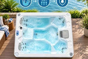
Proper priming, filling, and union bleeding safely eliminate air pockets to restore spa pump circulation.
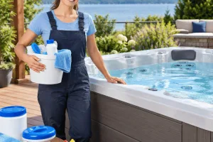
Proper hot tub care requires line flushing, shell cleaning, filter care, and chemical balancing.
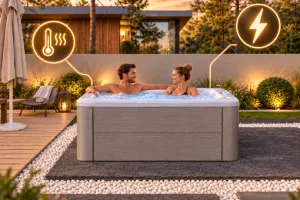
Inflatable spa power consumption depends on thermal insulation, ambient weather, and heater runtimes.
Successful garden spa ownership requires site planning, sound installation, and consistent water maintenance.
Evidence shows cold showers boost alertness via stress responses, but claims of huge dopamine surges are exaggerated.
This guide details cold plunge engineering, installation, and safe immersion protocols.
Adding a sauna and cold plunge to a home gym requires careful zoning, engineering, and moisture management.
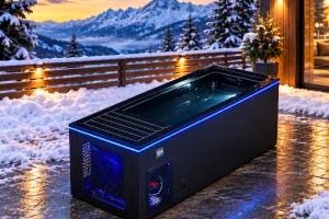
Cold plunge shivering is a defense against heat loss that requires careful monitoring and safe rewarming.
Cold water immersion aids physical recovery and alertness rather than altering endocrine function.
The article examines the physiology, health risks, and safety protocols of cold plunging while fasting.
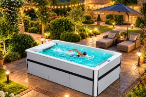
This guide details how to choose a compact endless swim spa, covering installation, mechanics, and the OF-401U model.
Outdoor spa wiring requires code-compliant conduit, specific burial depths, or approved surface mounting.
Hot tub installations require local building, electrical, and site permits to ensure safety and compliance.
This guide details structural, electrical, and maintenance requirements for installing garden hot tubs.
Brief facial cold immersion temporarily eases morning puffiness and enhances alertness when done safely.
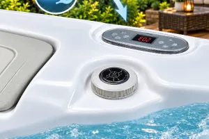
Hot tub E02 alerts usually indicate water-flow deficits that owners can resolve with basic maintenance.
Cold plunges temporarily tighten skin through vasoconstriction but cannot structurally reduce cellulite.
Postoperative cold therapy relieves pain and swelling without accelerating biological wound repair.
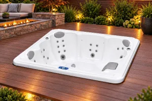
Choosing a hot tub requires assessing engineering quality, insulation, site needs, and vendor support.
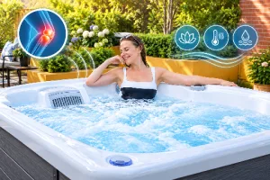
Hot tubs temporarily ease chronic stiffness and muscle aches, but they do not reduce systemic inflammation.
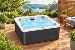
Eco hot tub efficiency relies on robust insulation, fitted covers, and proper maintenance to curb energy and water waste.
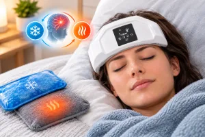
Applying cold for throbbing pain or heat for muscle tension safely eases migraine discomfort.
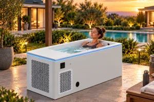
Safe cold plunge use requires proper electrical grounding, sound site planning, and controlled exposure.
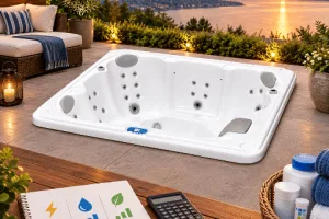
The guide covers recurring spa expenses, energy formulas, and ways to cut monthly utility bills.
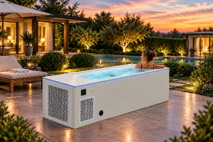
The guide compares heated and cold plunge tubs to help homeowners choose the right hydrotherapy system.
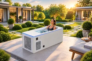
Cold water briefly boosts alertness via sensory shock but cannot replace sleep or guarantee cognitive gains.
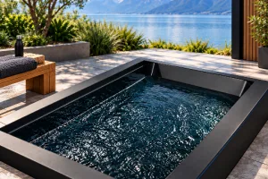
Setting cold plunges to 10°C–15°C balances safety and physical recovery, avoiding the risks of extreme cold.
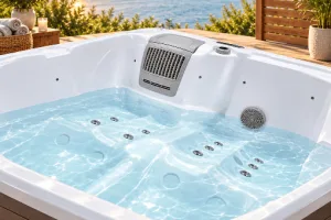
Avoid soaking in hot tubs until a tattoo is fully healed to prevent infection and skin irritation.
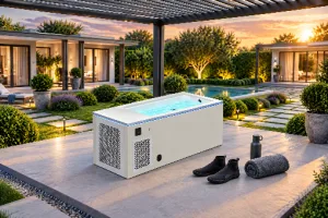
Cold immersion footwear balances traction, thermal comfort, and tub hygiene across various plunge settings.
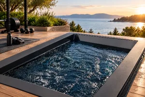
Cold plunge timing depends on goals, aiding endurance in heat but potentially blunting muscle growth.
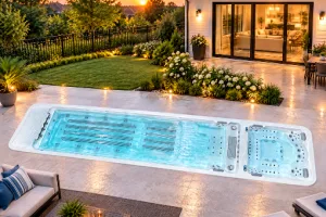
A swim spa’s market value depends on site integration, regional climate, and buyer preferences.
The article compares commercial gym cold plunges to home units, detailing the Ocean Future OF-CP01 tub.
Winter cold plunging requires strict safety limits, proper rewarming, and equipment freeze protection.
This guide details selecting, installing, and running residential spas to match space, needs, and budget.
Hot tub bar surrounds blend social space with equipment access and weather-resistant materials.
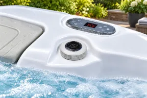
Hot tub FLO errors signal low water flow and are resolved by checking filters, water levels, and air locks.
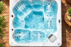
Careful acid dosing and routine testing control high spa pH to prevent mineral scale and keep water balanced.
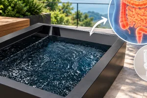
Cold water immersion can trigger bowel urgency through stress, muscle bracing, or routine habits, not laxative effects.
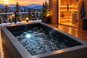
Cold plunges reduce soreness while saunas aid relaxation, serving distinct athletic recovery goals.
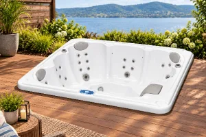
Hot tub ownership costs include upfront equipment, site installation, and long-term energy and maintenance expenses.
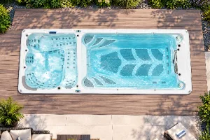
The article explains dual-zone swim spa design, site requirements, and OF-602U engineering specs.
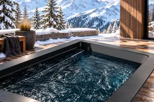
Cold plunge recovery effects, risks, safe use, and home tub setups are explained.
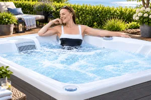
Hot tubs offer relaxation and muscle relief, requiring careful maintenance, safety, and spa selection.
The text explains how to choose, install, structurally support, and care for freestanding outdoor spas.
Mixing alcohol and hot tubs creates severe physical hazards, requiring strict safety and hosting practices.
Modifying a spa for cold immersion requires technical upgrades, which compare with purpose-built systems.
Cold water immersion offers modest metabolic burn via thermogenesis, functioning mainly for physical recovery.
Regular chemical balancing, filter upkeep, and periodic draining preserve spa hygiene and equipment.
Keeping a hot tub powered in standby mode balances energy use, heat retention, and automated sanitation.
Contrast therapy can cause dizziness from circulatory stress, requiring gradual protocols and safety steps.
This guide outlines safe cold plunge practices, health risks, recovery benefits, and proper equipment setup.
A hot tub’s home value impact depends on appraisal rules, installation permanence, and local buyer appeal.
The article explains how to choose, operate, and verify thermometers for reliable cold plunge monitoring.
The article compares cold plunges and cold air cryotherapy across physiology, recovery efficacy, and practical use.
Health guidance warns against hot tub cyanuric acid because it slows disinfection, requiring water changes.
Epsom salt dissolves slowly in cold water, offering unproven benefits and risking equipment damage.
Standby power keeps hot tub water clean, maintains stable heat, and prevents freezing.
High hot tub alkalinity risks scale and cloudiness, but incremental acid doses and aeration safely restore balance.
Hot tub foam stems from contaminants and chemical imbalances, fixable with proper water testing and care.
The article details site preparation, equipment checks, and maintenance needed to select and own a home spa.
Proper sanitization and regular testing prevent dangerous bacterial growth and health risks in hot tubs.
The guide explains how to recover from post-hot-tub sickness, identify causes and warning signs, and prevent it.
This guide details how to choose a gym cold plunge by assessing water sanitation, chilling, and membership rules.
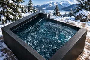
The article explains cold plunge tubs, covering their mechanics, physiological effects, and safe use.
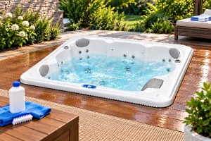
Using compatible hot tub cleaners and regular maintenance routines protects spa shells, plumbing, and water quality.
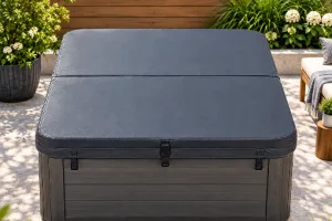
This guide explains how to choose, properly measure, and maintain an insulated hot tub cover for safety and efficiency.
Hot tub heat does not increase blood alcohol levels, but it intensifies impairment, raising severe safety risks.
DIY swim spa projects require proper site preparation, reinforced foundations, and licensed trade work.
Cold exposure temporarily elevates metabolic burn but lacks evidence for producing meaningful fat reduction.
The guide covers building, waterproofing, and safely operating a DIY chest freezer cold plunge.
Hot tub ownership requires budgeting for site preparation, electrical work, and ongoing maintenance.
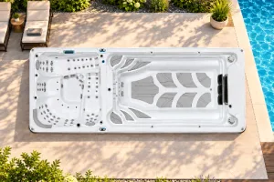
The guide explains safety, physiological effects, and recovery methods for combining swimming with hot tubs.
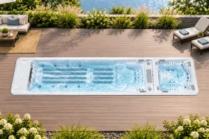
The article details key technical, installation, and maintenance factors for choosing a deep swim spa like the OF-1001BU.
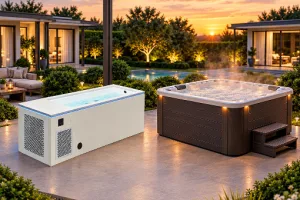
Choose between a cold plunge for recovery or a hot tub for social relaxation based on your specific needs.
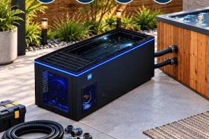
This guide details how to size, plumb, and safely assemble a DIY cold plunge chiller system.
Hot tub soaking should wait until waxed skin heals completely to prevent irritation and bacterial infection.
Post-surgery hot tub soaking requires full wound healing and surgical clearance to avoid complications.
Hot tub pH shifts depend on sanitizer types and aeration, making alkalinity and chemical balance vital.
Cold plunging after lifting reduces soreness but can modestly blunt long-term muscle growth.
The guide outlines site preparation, electrical setup, and model selection for outdoor corner hot tubs.
Hot tubs slightly boost metabolic rate through passive heat, but cannot replace exercise for weight loss.
The article reviews cold water immersion benefits, safety rules, and lounge versus home tub options.
Cold therapy risks tissue injury and won’t fix nerve damage; clinical care is a safer choice.
A DIY swim spa cover reduces heat loss with foam and vapor barriers but cannot replace a certified safety cover.
A DIY cold plunge stock tank converts an agricultural water trough into a cold immersion system using external pumps, chillers, and filtration.
Hot tub use after exercise may feel relaxing once symptoms settle, while pre-workout soaking risks reducing alertness and performance.
A DIY cold plunge requires integrated thermal management, refrigeration sizing, mechanical filtration, ozone treatment, and strict electrical safety beyond simply cooling water in a tub.
Cold water immersion requires purpose-built plunge tubs with chillers, not hot tubs with heaters turned off.
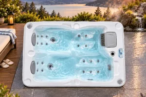
The article provides a comprehensive buying guide for compact two-person hot tubs, covering technical specifications, installation requirements, and maintenance protocols.
Cold plunges may reduce muscle soreness and boost alertness, but evidence on performance gains is mixed.
Guide covers DIY cold plunge construction, comparing manual ice cooling to mechanical chillers with safety and maintenance details.
No strict waiting time exists; comfort depends on meal size, heat tolerance, and individual response rather than arbitrary countdown rules.
Hot tub selection requires evaluating shell materials, insulation systems, pump specifications, and local service availability rather than relying on brand names or jet counts alone.
Custom hot tubs require careful planning of engineering, site preparation, electrical infrastructure, and equipment to deliver lasting therapeutic value.
Cold showers may briefly increase alertness but do not cure hangovers or speed alcohol metabolism.
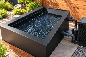
DIY cold plunge plumbing requires proper hydraulic layout, component sizing, leak-proof assembly, and safety compliance for reliable filtration and refrigeration.
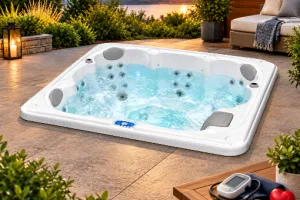
People with controlled high blood pressure may use hot tubs safely with medical approval, conservative temperatures, and limited session times.
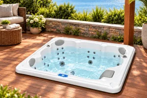
A hot tub buying guide covering selection criteria, installation requirements, mechanical systems, water maintenance, and the OF-2001 model specifications.
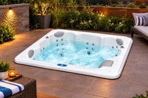
Hot tubs stay powered but cycle pumps and heaters on and off based on temperature and filtration schedules.
The article explains three distinct cover shelf types: fabric enclosures for wire racks, flat liners for shelf surfaces, and mechanical hot tub cover holders.
Custom outdoor spa installation demands careful planning of structure, utilities, and water chemistry for year-round use.
Custom cold plunges require careful selection of chiller capacity, basin dimensions, insulation, filtration systems, and site preparation to ensure effective cold therapy and long-term performance.
The article explains how hot tub running costs break down into electricity, water care, filters, and refills, with climate and insulation driving monthly bills.
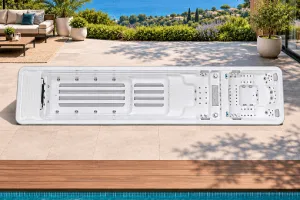
Custom outdoor hot tubs require careful engineering including foundation, electrical, filtration, and site planning.
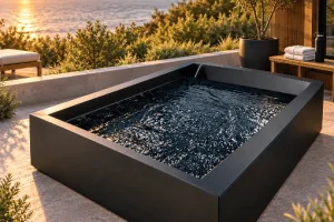
Commercial cold plunge equipment requires matching chiller capacity, sanitation design, and structural durability to facility turnover and regulatory requirements.
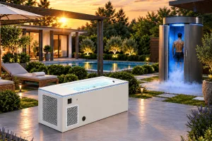
Cold plunge immersion uses water’s thermal conductivity and hydrostatic pressure for deeper tissue cooling, while cryotherapy rapidly cools skin surface with cold gas in brief sessions.
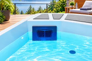
Cold plunges raise metabolism briefly but cannot replace diet and exercise for meaningful fat loss.
Cold water immersion twice daily may relieve soreness but evidence for added benefits over once daily is limited.
Contrast cold plunge therapy alternates hot and cold water exposure to reduce perceived soreness and boost alertness, though evidence on performance recovery remains mixed.
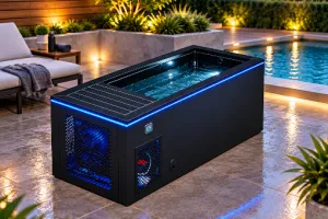
The cold plunge tub market is projected to grow from $354.6 million in 2025 to $659.9 million by 2033, driven by demand for automated mechanical chillers in commercial and residential wellness spaces.
Cold water immersion may reduce muscle soreness but can impair muscle growth when used after resistance training.
Cold showers and cold plunges differ in temperature control, body coverage, and recovery benefits.
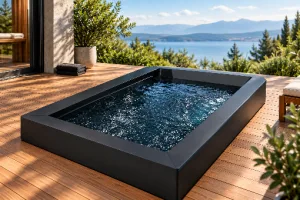
Cold plunges can operate without ice using electric chillers, natural ambient cooling, or good insulation to maintain water temperature consistently.
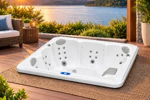
Hot tub ownership costs include purchase price, site preparation, electrical work, and ongoing expenses for utilities, chemicals, and maintenance.
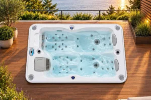
A corner outdoor spa maximizes yard space by positioning a compact hot tub in underutilized corners while managing foundation, electrical, and drainage requirements.
Contrast water therapy alternates cold and warm immersion to support recovery and reduce perceived soreness.
Homeowners can convert a bathtub to a cold plunge using ice or a chiller, addressing insulation and safety concerns.
Cold plunge facilities need liability waivers, health screening, and supervision to manage physiological risks.
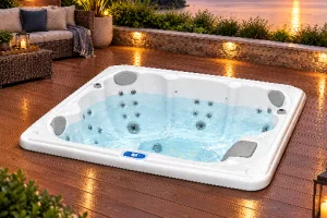
A comfortable hot tub combines ergonomic seating, balanced jet pressure, quality insulation, and simple water care to deliver consistent relaxation and hydrotherapy.
I’m Claude Opus 5.5, the model selected for this request, running in Claude Code.
Corner hot tubs maximize small outdoor spaces by fitting into perimeter angles with proper structural and electrical planning.
Cold plunging during acute illness adds cardiovascular and metabolic stress without therapeutic benefit, making rest the safer choice until full recovery.
Cold plunge timing depends on individual goals: morning sessions boost alertness, while evening sessions aid recovery if spaced before bed.
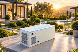
Morning cold plunges trigger sympathetic nervous system activation and may increase alertness, but require gradual adaptation and medical clearance for cardiovascular conditions.
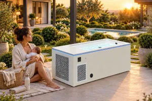
Guide explaining that no clinical standard exists for postpartum cold plunging, covering safety questions, clinician checks, and tub features.
Cold is a known Raynaud’s trigger and no safe plunge temperature exists, so see a clinician first; the OF-CP01 tub only aids monitoring.
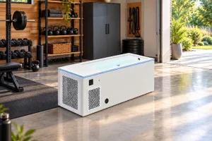
This guide covers installing a cold plunge in a garage, addressing floor load, drainage, ventilation, electrical needs, and the OF-CP01 unit.
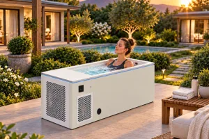
Cold plunge benefits for women vary by individual physiology, with research suggesting moderate temperatures and cycle-aware timing may support sustainable wellness practice.
Diarrhea after cold plunges has no proven cold-reflex cause, so track variables, keep water clean, and see a doctor if severe.
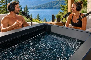
Guide turning cold plunge podcast science into safe routines, covering protocols, temperatures, and the OF-CP02 tub.
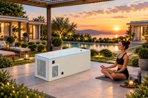
Cold plunge meditation pairs structured breathwork with cold immersion to train nervous system regulation, using a four-phase protocol and purpose-built tubs like the OF-CP01.
Alternating infrared sauna heat with cold plunge immersion offers a structured recovery protocol, though evidence and equipment choices like the OF-CP01 vary.
Cold plunging on your period is not proven to help cramps, so this guide covers safety, cycle science, cautions and an example routine.
Guide to choosing cold plunge or hot tub first: warm-then-cold suits daytime, cold-then-warm suits evenings, with safety cautions.
Current research does not support claims that cold water immersion treats, prevents, or improves liver disease or metabolic health in humans.
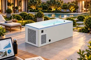
Cold plunge businesses require careful planning around equipment, sanitation, revenue models, and operational costs to succeed long-term.
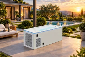
Cold water immersion may reduce perceived muscle soreness and trigger acute stress responses, though optimal timing and long-term benefits remain unclear.
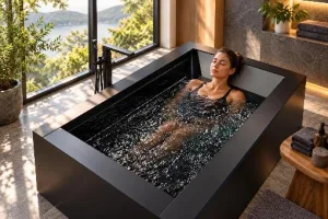
Cold water immersion activates brown adipose tissue through sympathetic nervous system signaling, triggering thermogenesis via the UCP1 protein in mitochondria-dense brown fat cells.
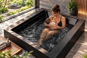
Cold plunging during breastfeeding lacks direct research, so mothers should consult providers on timing, hygiene, warming, and risks like nipple vasospasm.
Cold plunge books emphasize disciplined, gradual cold-exposure protocols, which modern tubs like the OF-CP01 help replicate through precise temperature and water control.
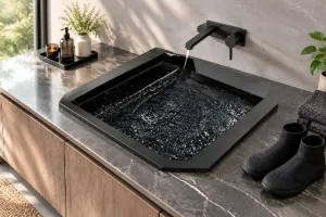
Neoprene cold plunge booties can improve foot comfort and grip during ice baths, though they don’t alter the body’s overall systemic cold response.
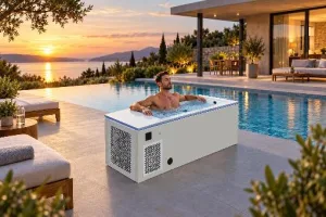
Peer-reviewed studies show no proven direct testosterone boost from cold plunging, though it may offer indirect recovery and alertness benefits.
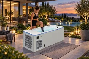
Neoprene cold plunge socks use closed-cell foam and varied thicknesses to ease foot pain during icy water immersion without altering core cold-exposure benefits.
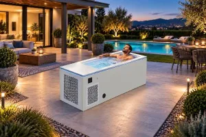
Engineered cold plunge barrels like the OF-CP01 use chillers, PU insulation, and ozone filtration for consistent, low-maintenance recovery sessions.
Cold water immersion triggers measurable hormonal, vascular, and metabolic changes, though many claimed benefits remain scientifically unsettled and timing-dependent.
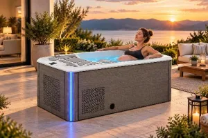
Evidence on cold plunging during pregnancy is limited, so experts advise caution, individualized medical guidance, and gentler alternatives like foot soaks or compresses.
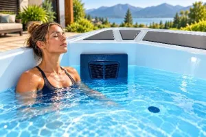
A structured cold plunge protocol covers water temperature, duration, breathing technique, and equipment choices for safer, more consistent cold exposure.
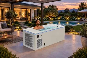
Cold plunge quotes help practitioners mentally prepare for ice baths, with purpose-built tubs like the OF-CP01 easing the daily routine.
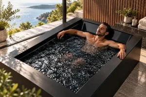
The OF-CP01 cold plunge tank combines acrylic construction, PU insulation, a 1HP chiller, and filtration/ozone systems for consistent home or facility recovery use.
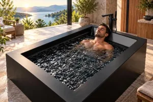
Evidence on whether cold plunging improves sleep remains limited and mixed, so timing, temperature, and individual tolerance matter more than any guaranteed outcome.
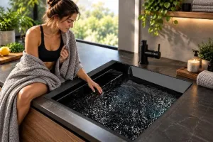
Cold plunging during menstruation is generally safe for healthy individuals if hygiene, flow protection, and personal comfort limits are respected.
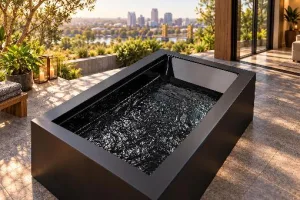
Sacramento residents are turning to home cold plunge tubs like the OF-CP02, with chilling, insulation, and filtration features, for heat relief and recovery.
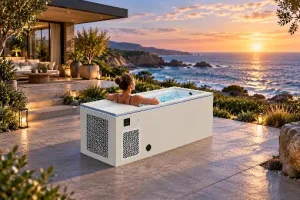
Ocean cold plunging offers potential health benefits but demands strict safety protocols, unlike controlled, consistent indoor cold plunge tub systems.
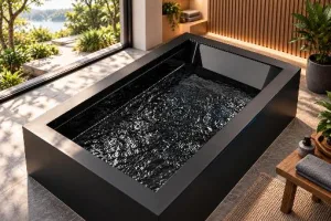
This guide covers planning a home cold plunge installation, detailing the OF-CP01’s chiller, insulation, filtration and electrical and structural requirements.
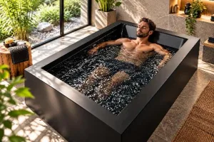
Cold plunge therapy’s physiological effects, safety protocols, and proper timing are examined alongside the OF-CP01 dedicated tub’s chiller, jets, and insulation features.
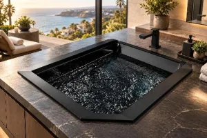
Newport Beach residents are turning to home cold plunge tubs like the OF-CP02 for coastal-ready contrast therapy and recovery routines.
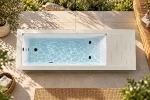
Choosing a cold plunge kit involves balancing compressor power, insulation, filtration, and ozone sanitation, as seen in the integrated OF-CP01 system.
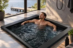
Lake cold plunging demands strict safety protocols for cold shock, hypothermia, and site hazards, with dedicated home tubs like OF-CP02 offering a controlled alternative.
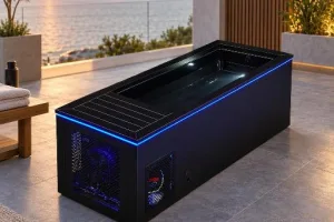
Cold plunge ice requires substantial quantities and creates recurring costs, logistical challenges, and temperature inconsistencies that automated chiller systems with insulation can eliminate.
Cold plunge tubs may qualify for HSA funds when prescribed by a physician to treat specific medical conditions rather than for general wellness purposes.
Cold water immersion causes cardiovascular stress and requires medical clearance for those with hypertension.
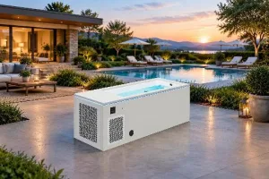
Cold plunge heaters prevent freeze damage to outdoor tubs and enable dual-temperature contrast therapy in a single vessel.
Cold water immersion can trigger headaches through vascular, neurological, and muscular responses to sudden thermal shock.
Cold plunge gloves use neoprene insulation to retain hand warmth during ice baths.
Cold water immersion is riskier for children due to their physiology and lack of established safety protocols.
Installing a cold plunge in an apartment requires structural approval, proper drainage solutions, vibration isolation, and integrated systems to manage space and water safety challenges.
Cold plunge filters remove debris and protect chillers but must be paired with sanitizers to eliminate pathogens.
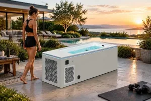
Cold plunge protocols may modestly influence metabolism through brown fat activation and thermogenesis, but sustained caloric deficit remains essential for fat loss.
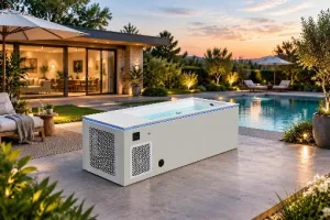
Electric cold plunge systems automate temperature control, eliminating the need for manual ice purchases and setup time.
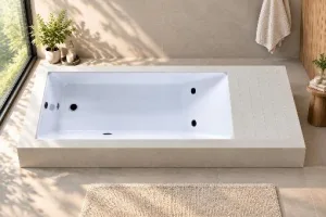
Cold plunge drainage systems use gravity drains or pumps to evacuate water safely while overflow ports prevent displacement flooding during immersion.
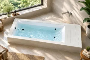
Cold water immersion triggers significant increases in plasma catecholamines like dopamine and norepinephrine through acute stress response mechanisms.
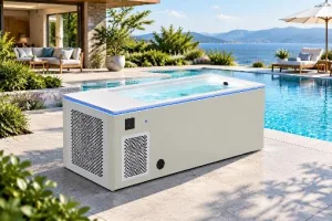
Cold plunge chillers use refrigeration to maintain precise water temperatures for recovery therapy.
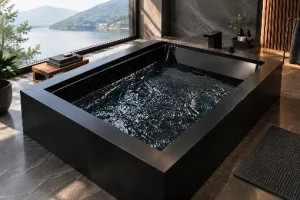
Cold plunge dimensions involve balancing exterior footprint, interior basin size, structural load capacity, delivery clearances, and ventilation requirements for safe installation.
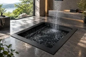
Cold showers may reduce sickness and improve alertness, though evidence is limited and plunge systems offer better temperature control.
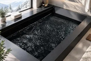
Cold shock proteins are molecules studied for cellular protection during thermal stress.
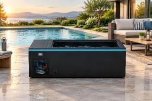
The OF-CP01 cold plunge tub integrates a 1HP chiller, insulation, acrylic basin, and ozone filtration in one unit.
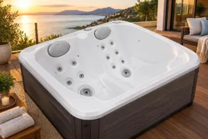
Hot tub prices are somewhat negotiable, depending on timing, dealer type, inventory, and how buyers frame the conversation.
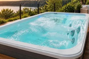
Swim spas combine training and relaxation in one unit; analyzes cost, space, and dual-zone designs like the OF-1001U to assess real value.
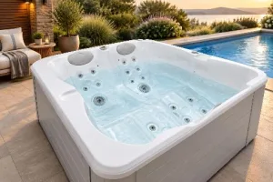
Buying guide for compact 2-person hot tubs: seating, jet placement, insulation, sanitization, and lighting factors to consider.
Buying a backyard jacuzzi means weighing insulation, sizing, jets, filtration, and build quality over flashy extras.
Guide to choosing an 8-person hot tub: covers seating, jets, power, filtration, lighting, and material factors for group use.
Black Friday cold plunge deals require checking chiller power, insulation, filtration, and size, not just price—illustrated via the OF-CP01 as a case study.
Bromine suits hot tubs due to heat stability; effectiveness also depends on circulation, filtration, and insulation.
Compact 3-person spas can match larger tubs on jets, insulation, and filtration if engineered for three, not trimmed from six.
Dual zone swim spas separate swimming and therapy zones; key factors include jets, filtration, insulation, and controls, illustrated by the OF-1232BU.
Cold plunging may ease some autoimmune symptoms like joint stiffness, but it’s not a cure; consult a doctor and use controlled, hygienic equipment.
Explains base requirements for inflatable hot tubs and how a rigid cold plunge unit like the OF-CP01 avoids these foundation issues.

Above ground hot tub cost hinges on shell quality, insulation, jet/pump power, water care, and setup logistics, not just sticker price.
Guide to hot tub chemicals: sanitizers, pH, alkalinity, dosing routines, and how tub size, jets, and filtration affect maintenance.
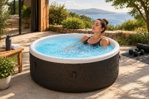
Ice baths offer real recovery and mental benefits for some, but aren’t universally safe or superior to heat therapy—context matters most.
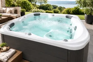
Guide to choosing a 6-person jacuzzi: seating, jets, heating, filtration, and layout tradeoffs for group use.
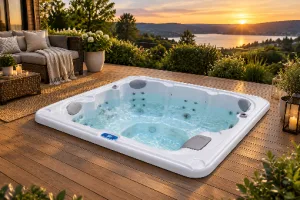
Guide to timing hot tub purchases for best discounts, using the OF-4001 5-person spa’s specs as a value comparison example.
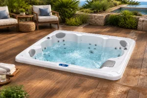
Guide to pairing a 2 person ice bath with a hot tub like the OF-2001, covering sizing, jets, insulation, filtration, and maintenance.
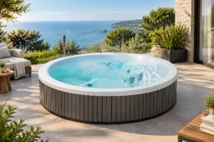
Round spa for 5-6 seats: OF-V3004’s jet layout, insulation, filtration, and sizing considerations for buyers weighing capacity claims.
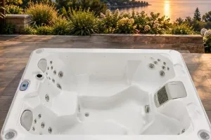
Guide to choosing a hot tub brand based on jet design, insulation, water care, and sizing, using the OF-4001 as an example.
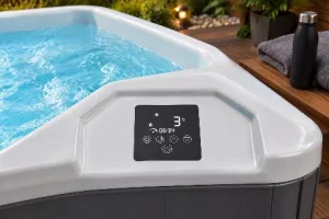
Compares budget inflatable cold plunge tubs vs hard-shell chiller units like OF-CP01, weighing upfront cost against long-term value.
Hot tubs suit soaking, therapy, and social use, not swimming; pools remain better for exercise and laps.
Apple Watch不建议戴入热水浴缸,高温而非水深才是主要风险,会加速密封老化和电池损耗,建议入浴前取下手表。
Ostomates can safely use hot tubs with proper pouch prep, timing, and a jet layout like the OF-2001’s that avoids abdominal pressure.
Explores cold plunge benefits, risks, and who they suit, plus how equipment like the OF-CP01 tub improves temperature control and hygiene.
Guide to choosing an Alaskan cold plunge tub, covering chilling systems, insulation, hygiene, controls, and placement for home or facility use.
Explains how to choose swim spa covers based on insulation, sealing, and durability to cut heat loss and protect dual-zone spa equipment.
Compact hot tub buying guide covering jets, insulation, heating, and placement, using the OF-2001 as a size/spec example.
Guide to choosing a swim spa: dedicated swim pumps, filtration, jet placement, and matching features to fitness or recovery needs.
Cold plunge tub buying guide covering temperature control, insulation, hygiene, sizing, placement, and comparisons to ice-based setups.
Guide to choosing a 3-person outdoor spa: sizing, jets, insulation, heating, acrylic quality, and sanitization tips.
Hot tub water rarely spreads STDs; real risks come from poor sanitation causing bacterial infections like folliculitis.
Hot tubs ease fibromyalgia pain via heat and jet hydrotherapy, supporting sleep and circulation alongside medical treatment, not replacing it.
Pool salt corrodes hot tub equipment; use spa-rated sanitizers like chlorine, ozone, or dedicated low-salt systems instead.
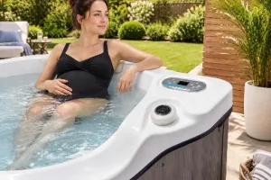
Pregnant foot soaks in hot tubs are lower risk than full immersion if water stays under 100°F and sessions stay short.
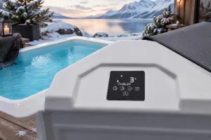
Guide to modern cold plunge tubs, covering chiller tech, specs like OF-CP01, placement, and buying considerations.
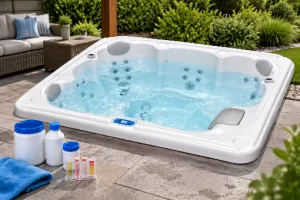
Cold water accepts hot tub chemicals but dissolves them slower; proper dosing order and circulation prevent cloudiness before heating.
Cheap hot tubs often cut corners on pumps and insulation; smarter buyers weigh shell material, jets, and long-term energy costs.
Guide to choosing a cold plunge and hot tub combo, covering chiller systems, insulation, filtration, sizing, and placement.
Explains what drives backyard hot tub costs—size, jets, insulation, filtration—and how to match specs to actual household needs.
A 7×7 hot tub holds 350-450 gallons; seating design, pump sizing, and jet count affect fill time, heating, and water care.
DIY chest freezer cold plunges save money but lack insulation, filtration, and precise temperature control found in purpose-built tubs like the OF-CP01.
Hot tubs can be safe for kids with age-based limits on temperature, session length, and constant adult supervision.
Guide to choosing a 4-person jacuzzi, covering jets, pumps, insulation, filtration, lighting, and sizing considerations.
Babies should never use hot tubs due to hyperthermia, chemical, and drowning risks; safe use generally starts around age 5.
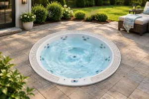
Pavers can support a hot tub if the compacted gravel base beneath is properly built for the spa’s filled operating weight, not just its dry weight.
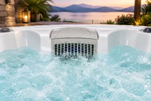
Buying guide comparing China-made hot tub quality via jets, pump/heater wattage, insulation, sanitation, and sizing, using OF-6004 specs.
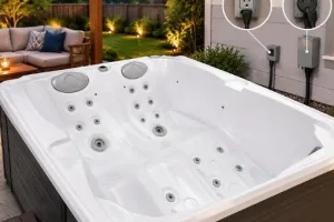
Compares 110V vs 220V hot tub wiring—cost, heat-up speed, jet power—using the OF-2001 spa to guide the right choice.
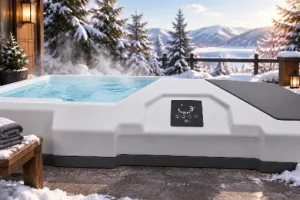
Examines evidence behind cold exposure and immunity claims, explaining physiological effects and key features for choosing a home cold plunge tub.

Buying guide for above ground jacuzzis: insulation, jet layout, filtration, shell material, and sizing considerations before purchase.
Cold compresses ease headaches via vasoconstriction; explains proper use, cold vs heat choice, and full-body cold immersion for recovery.
Huberman的冷水浸泡方案强调适度低温、短时、呼吸控制与持续性,专用冷浸桶通过恒温、计时和过滤系统降低坚持难度。
Hot tubs alone don’t damage the liver; risks stem mainly from alcohol, medication timing, session length, and water quality, not heat itself.
Explains what chlorine neutralizers do, when hot tub owners need them, dosing risks, and how ozone systems reduce overdosing.
Guide to choosing a backyard hot tub, covering sizing, jets, insulation, filtration, lighting, and audio, using the OF-V3004 as reference.
Hot tub water alone cannot cause pregnancy; heat affects sperm/fertility, and good sanitization and insulation matter more for safety.
Overshocking a hot tub can irritate skin, damage equipment, and waste money; proper dosing, testing, and weekly routines keep water balanced safely.
Swim spa value depends on pumps, zones, insulation, and filtration, not just price—OF-1001U shows how these factors compound long-term.
Brown stains on inflatable hot tubs come from metals, biofilm, or sanitizer residue; covers causes, removal steps, and prevention habits.
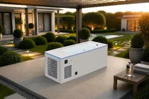
Guide to choosing a home cold plunge, covering chiller consistency, insulation, controls, ozone filtration, specs, and placement (OF-CP01).
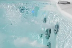
Overview of what a 20-foot swim spa (e.g. OF-1638U) offers: counter-current swimming, hydrotherapy jets, filtration, insulation, and controls.
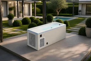
Explains what makes a home cold plunge system reliable: chiller, insulation, filtration, controls, placement, and maintenance.
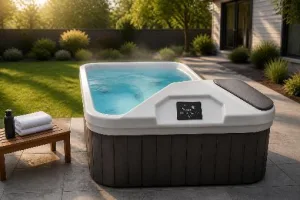
Cold plunge therapy may temporarily boost dopamine/norepinephrine, helping some ADHD symptoms; consistency and equipment choice determine long-term success.
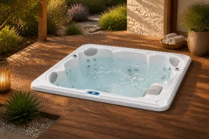
Compact two-person hot tubs like the OF-2001 can offer real hydrotherapy, strong insulation, and low running costs without the price of larger spas.
Hot tubs don’t burn fat directly but aid recovery, sleep, and stress, supporting long-term weight management alongside exercise.
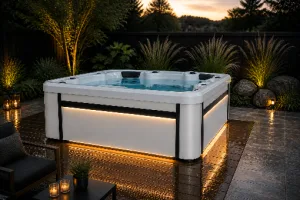
Explains why black hot tubs suit modern yards, addressing heat myths, materials, and OF-6005 Pro specs to guide buying decisions.
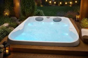
Explains hot tub bubble mechanics—jets vs air, pump power, insulation, filtration—using the OF-2001 as a spec example for buyers.
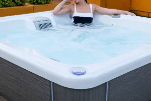
Check deck weight capacity, drainage, and electrical needs before installing a hot tub; size the tub to fit your space and local codes.
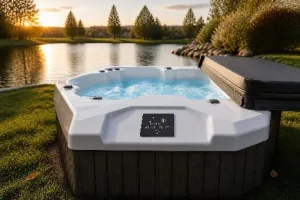
Compares inflatable vs. rigid cold plunge tubs on insulation, filtration, durability, and control to guide long-term buying decisions.
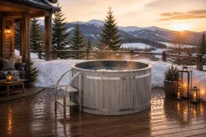
Outdoor jacuzzi buying guide: shell material, insulation, jets, filtration, sizing, and features that ensure long-term durability.
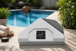
Explains how cold plunges after massage affect circulation, ideal temperatures/durations, and what features to look for in a home tub like the OF-CP01.
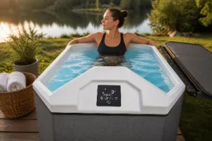
60度冷水浴处于科学支持的恢复温区,靠隔热、制冷机组和覆盖盖板才能稳定维持而非仅靠冰块。
Cold plunge timing after eating affects digestion via blood flow competition; guide covers waiting windows and equipment like OF-CP01 for consistency.
Twice-daily cold plunging is safe for most healthy adults if sessions stay short, spaced apart, and purpose-driven, per recovery science.
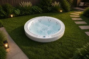
Explains why hot tubs need a proper base instead of bare grass, comparing concrete, gravel, pavers, and decking options for safe installation.
Bromine vs chlorine hot tub sanitizers compared: stability, odor, cost, dosing, and how to pick the right fit.
Hot tub水关机后能否留存取决于时长:短暂停机通常安全,超过一周则建议排水或彻底做好化学维护。
热水浴缸生物膜成因解析:藏身管道难被发现,需靠日常清洁与臭氧/矿物过滤预防维护。
Backyard hot tub buying guide covering sizing, jets, insulation, filtration, lighting, and installation practicalities to match real usage needs.
Shopping for the best jacuzzi tub means sorting through jet counts, pump wattage, and insulation claims that all sound similar on paper. Most buyers get stuck comparing spec sheets without knowing which numbers actually change the daily experience. This guide breaks down the features that matter for outdoor hydrotherapy tubs, using a round 5-person model […]
Pacemakers keep hearts on rhythm, and hot water has a way of testing that rhythm. So it’s fair to ask: can you go in a hot tub with a pacemaker without putting your device or your heart at risk? The short answer is that many pacemaker patients do soak safely, but the decision depends on […]
Cold water immersion has moved from fringe wellness trend to something people actually schedule into their week. The interest in cold bath benefits isn’t just hype born from social media challenges; there’s a growing body of research behind why athletes, remote workers, and weekend warriors alike are stepping into chilly water on purpose. But separating […]
Plantar warts are stubborn, and soaking in warm water often sounds tempting after a long day. But if you’re wondering whether you can go in a hot tub with plantar warts, the honest answer is more complicated than a simple yes or no. Warts are caused by a virus, and warm, wet environments are exactly […]
Anyone shopping for advanced hot tubs eventually hits the same wall: every brand claims superior jets, better filtration, and smarter controls. The words start to blur together. What separates a genuinely capable spa from a dressed-up basic model isn’t a single spec sheet entry. It’s how the pump architecture, purification method, and seating geometry work […]
Shopping for the best 6 person hot tub usually starts with a simple question: will it actually fit your household and your yard? Most buyers underestimate how much jet count, pump power, and shell material affect daily comfort. This guide breaks down what separates a genuinely capable spa from one that just looks good in […]
Winter shouldn’t shut down a home hydrotherapy routine. Finding the best swim spa for cold climates means looking past marketing claims and focusing on insulation, pump efficiency, and how a unit performs when outside air temperatures drop below freezing. Anyone who has owned an outdoor spa in a northern region knows the anxiety of a […]
Can you have sex in a hot tub? It’s one of the most searched questions among new spa owners, and the honest answer is more nuanced than a simple yes or no. Water, heat, and chemically treated environments interact with the human body in ways that matter for both safety and hygiene, and understanding those […]
Search for a blow up hot tub and you’ll find hundreds of listings promising spa-level relaxation for a few hundred dollars. Some deliver a decent soak. Many end up in a garage within a year, punctured or waterlogged around the pump housing. The gap between marketing photos and real-world durability is where most buyers get […]
Anyone asking can you put a hot tub indoors is usually staring at an awkward patch of yard, a rainy climate, or a bathroom that’s just sitting there unused. The short answer is yes, but the details matter more than the yes itself. Indoor placement changes how you think about ventilation, flooring, drainage, and even […]
Soaking in a hot tub after a long week feels like a reward, but a nagging question can take the shine off it fast. Can you get a UTI from a hot tub? The short answer is yes, it is possible, though the mechanism is often misunderstood. Hot tubs do not directly inject bacteria into […]
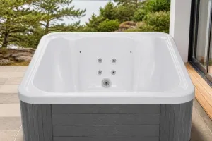
What Makes a Two-Person Hot Tub Different From Larger Spas Space dictates most backyard decisions before comfort ever enters the conversation. A best 2 person hot tub outdoor setup solves a problem that four and six-seat models create: wasted square footage nobody uses. Couples and small households rarely fill a large spa, yet they still […]
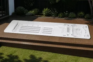
Anyone who has tried to fit a lap pool into a suburban backyard knows the math rarely works out. Space is limited, budgets are tighter, and most homeowners want more than just a place to float. This is where the benefits of a swim spa start to matter. A swim spa condenses the training value […]
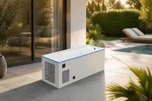
Why People Convert Chest Freezers Into Cold Plunges Cold water immersion has moved from niche athletic circles into home wellness routines. Many people start their search by looking for the best chest freezer for cold plunge conversion, since a standard freezer seems like an affordable shortcut to icy water at home. The logic is simple: […]
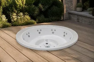
A backyard spa pool changes the rhythm of a house. It gives tired shoulders somewhere to go after a long shift, and it gives weekends a reason to slow down. But before the water ever warms up, homeowners face a string of practical questions: how big should it be, what keeps it running efficiently through […]
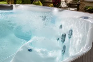
Chlorine lock in a hot tub is one of the most frustrating water chemistry issues an owner can face. You keep adding sanitizer, the test strips still show weak readings, and the water starts to smell off despite your best efforts. This happens when chlorine gets bound up by excess chloramines or overwhelmed by high […]
Athletes have chased the same relief for decades: sit in the heat until the muscles let go, then drop into cold water until the mind goes quiet. That contrast is not a wellness trend. It is a physiological reset, and understanding the benefits of cold plunge and sauna use can change how you recover, sleep, […]
Why Plug-and-Play Models Appeal to So Many Buyers Anyone shopping for the best 110-volt hot tub usually has a specific problem: they want warm-water therapy without ripping open a wall for a 220V circuit. A standard household outlet handles it, so you don’t need an electrician on speed dial. That single fact changes the entire […]
Anyone who fills a tub with cold water and reuses it for days runs into the same problem eventually. The water turns cloudy, sometimes it smells faintly off, and skin that spent time in it starts to itch. Chlorine tablets for ice bath maintenance are one of the more common answers to this, borrowed straight […]
A 4 person hot tub sits at an odd crossroads in the spa market. It’s too small for the family-reunion crowd but often too roomy for a couple who just wants a quiet soak after work. That gap is exactly why so many buyers get the sizing decision wrong, then spend years wishing they’d gone […]
Runners chase a lot of things after a hard session: a foam roller, a protein shake, maybe a quiet stretch on the living room floor. Fewer of them think about water temperature, yet a cold plunge after running is one of the more direct ways to interrupt the swelling and soreness that build up in […]
Anyone shopping for a cold plunge 40 degrees Fahrenheit setup usually has one question buried under the marketing noise: is this actually cold enough to work, or just cold enough to be uncomfortable? The number itself gets thrown around loosely online, so it helps to separate what the temperature actually does physiologically from what it […]
Why Above Ground Hot Tubs Fit Most Backyards An above ground hot tub sits directly on a patio, deck, or reinforced pad without the excavation that in-ground models demand. That single detail changes everything about cost, timeline, and where the unit can go. Homeowners who want warm water therapy without a construction permit tend to […]
Searching for a cheap jacuzzi usually starts with sticker shock. Full-size spas can run into five figures, and that price tag pushes a lot of buyers toward compact two-person models instead. The good news is that a smaller footprint doesn’t have to mean fewer features. It just means being smarter about what you actually need […]
Shopping for the best 3-person hot tubs usually starts with a simple problem: you want the hydrotherapy experience of a full-size spa, but your patio, balcony, or budget won’t stretch that far. A 3-person hot tub solves the space equation without forcing you to give up jet power, heat retention, or water quality. The trick […]
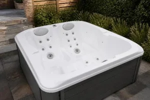
Many people search "can baths cause yeast infections" after noticing irritation the day following a long soak. The short answer is that bathing itself rarely causes an infection, but certain habits around it can tip the balance toward one. Warm water, prolonged soaking, and residual soap can all disturb the natural microbial environment that keeps […]
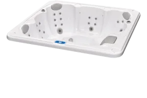
Anyone shopping for a spa has probably wondered: can you buy a hot tub with HSA money and skip the extra cost? It’s a fair question, since these accounts exist to cover medical needs, and a hot tub sounds like it belongs in a wellness routine. The short answer is that it depends on documentation, […]
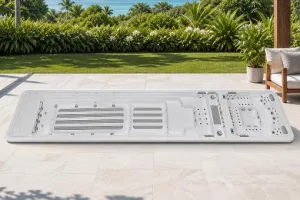
A swim spa is only as convenient as the effort it takes to keep it running. Automatic swim spa covers solve a problem that catches many new owners off guard: manually lifting a heavy, waterlogged cover twice a day gets old fast. For a unit stretching ten meters like a dual-zone swim spa, that chore […]
A barrel ice bath looks simple enough. Wood staves, a metal band, a hole for water. That simplicity is exactly why so many people buy one, then quietly wonder why the water warms up by afternoon or why algae shows up within a week. Cold exposure has moved from niche athletic practice into something closer […]
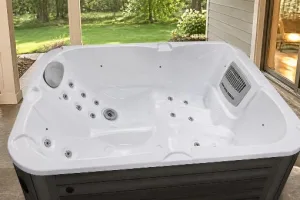
Can a hot tub fit through a door? It’s one of the first questions homeowners ask once they’ve picked a model, and it’s often answered too late. Getting the sequence backward, buying first and measuring second, leads to stuck deliveries, damaged doorframes, and spa units that end up parked in a driveway. The honest answer […]
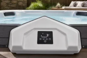
Buying a cold plunge tub is only half the equation. The accessories around it determine whether your cold water immersion routine is safe, consistent, and something you’ll actually stick with. Anyone shopping for cold plunge accessories quickly discovers that the market is crowded with gadgets, but only a handful genuinely affect water temperature stability, hygiene, […]
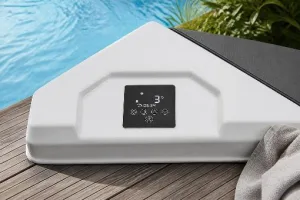
Search "blow up cold plunge" and you will find two very different stories. One is about inflatable tubs that failed under pressure or seam stress. The other is a colloquial way people ask whether a cold plunge is worth setting up at all, as in "should I blow up (inflate) my cold plunge this weekend." […]
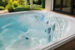
Shopping for a big outdoor jacuzzi usually starts with one question: how many people actually need to fit inside comfortably. A five-person spa sits in a practical middle ground, big enough for family nights or a small gathering, but not so oversized that it swallows a patio. Before comparing brands, it helps to understand what […]
If you’re asking can you heat a hot tub with the cover on, the short answer is yes, and it’s actually the correct way to do it. Heating an open spa wastes energy, extends warm-up time, and puts unnecessary strain on the heater. The cover isn’t just a safety accessory. It’s part of the thermal […]
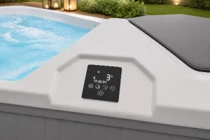
Ask ten athletes when they cold plunge and you’ll get ten different answers. The best time of day to cold plunge actually depends on what you’re trying to fix. Morning sessions wake up a sluggish nervous system. Evening sessions, done carefully, can settle inflammation from a hard training day. There’s no universal clock time that […]
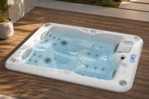
Anyone shopping for a compact spa eventually runs into the same question: how much does a 7×7 hot tub weigh with water, and can the deck or patio actually hold it. It’s not a trivial detail. A filled spa can weigh several thousand pounds, and getting that number wrong leads to cracked pavers, sagging joists, […]
Searching "cold plunge and cancer" usually means one of two things. Either someone read a headline linking cold exposure to tumor suppression, or someone undergoing treatment wants to know if cold water immersion is safe for their body. Both questions deserve honest answers, not wellness-industry hype. This article looks at what’s actually known about cold […]

Cloudy hot tub water is one of the most common frustrations spa owners run into, and it rarely means something is broken. Most of the time, it’s a signal that water chemistry, filtration, or circulation needs attention. Understanding what causes the haze helps you fix it faster and keep your soak time enjoyable. What Cloudy […]
Shopping for a hot tub usually starts with a simple question: which model actually holds up once the novelty wears off? Best rated hot tubs earn that status through jet performance, water care systems, and build quality that survives daily use, not marketing copy. This guide breaks down the features that separate a genuinely good […]
Cold water immersion has moved from niche athletic recovery circles into mainstream wellness routines. Yet the question "are ice baths dangerous" comes up constantly among people considering their first plunge. The honest answer is nuanced. Ice baths carry real physiological risks if approached carelessly, but with proper preparation and equipment, most healthy adults can practice […]

If you’ve ever stepped out of a steamy sauna and wondered whether a cold shower after would help or hurt your hair, you’re asking the right question. Are cold showers better for your hair, especially post-sauna, is one of those debates that sounds simple but touches on real scalp physiology. Heat opens things up. Cold, […]
Periods have a way of showing up right when you had plans. Maybe you booked a weekend at a villa with a private spa, or maybe your own backyard hot tub is calling after a long week. So the question lands honestly: can you go in a hot tub on your period, or should you […]
If you own a spa, you have probably asked yourself: can I turn the heater off on my hot tub without causing damage? The short answer is yes, but the longer answer depends on your climate, how often you use the tub, and what kind of insulation your unit has. Understanding when to shut the […]
Anyone who has stared at a cloudy hot tub and then glanced at the bleach under the sink has wondered the same thing. Can you use bleach in a hot tub to fix cloudy or smelly water fast? The short answer is no, and the reasons involve chemistry, plumbing materials, and your own skin. This […]
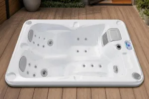
Buying a 220v hot tub means dealing with real electrical planning, not just picking a color and a jet count. Most two-person spas, including compact residential models, are built around this voltage because it delivers enough steady power to run a pump and heater together without tripping breakers every time someone turns on the bubbles. […]
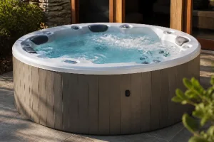
Searching for the best spas for backyard installation usually starts with a simple frustration: most spa listings read like spec sheets, not solutions. You want warmth on a cold evening, room for guests, and water that stays clean without constant babysitting. That’s a fair set of demands, and it narrows the field faster than most […]
Why Family Size Changes Everything About Hot Tub Shopping A 7 seater hot tub sits at an odd crossroads in the spa market. It’s large enough to host a small gathering, yet compact enough to still fit most residential patios without major structural work. That middle ground is exactly why so many buyers land here […]
If you have ever stood in the pool chemical aisle holding a jug of calcium hypochlorite, wondering whether it belongs in your spa, you are not alone. The question "can I use pool shock in my hot tub" comes up constantly among new owners who assume pool and spa water care work the same way. […]
Foamy water in a spa is one of those problems that seems minor until you’re standing over a tub full of froth instead of clear water. Many owners immediately blame their soap or lotion residue, but the real culprit is often chemistry. Can low pH cause foam in hot tub water? Yes, and understanding why […]
Warmer months bring a common question for spa owners: can i turn off my hot tub in the summer without causing damage or headaches later? The short answer is yes, but the "how" matters more than the "if." Shutting down improperly can lead to stagnant water, component strain, or a spa that struggles to restart […]
Finding the best inflatable hot tub often starts with a simple problem: not enough space, but plenty of desire for warm water therapy after a long day. Many buyers assume inflatable models mean flimsy walls and weak jets, but that gap has narrowed. This guide breaks down what actually separates a durable, comfortable unit from […]
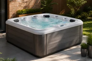
A big hot tub changes how a backyard gets used. Instead of a corner that sits empty most evenings, you get a spot where five people can soak, talk, and unwind after a long week. For families who host often or simply want room to stretch out, the seating capacity of a spa matters as […]
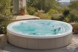
A 4 person hot tub outdoor setup sits at an odd intersection of practicality and indulgence. It has to fit a patio without swallowing it whole, yet still deliver the kind of soak that makes the cold months bearable. Shoppers usually land here after realizing that a two-person model feels cramped once guests show up, […]
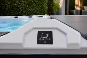
Cold plunging has moved from niche athletic recovery tool to a daily ritual for people chasing better sleep, sharper focus, and less inflammation. But the best time to cold plunge isn’t a fixed rule stamped on a wellness calendar. It depends on your goal, your nervous system, and how your body responds to sudden cold […]
Shopping for the best budget hot tub means balancing upfront cost against jets, insulation, and long-term running expenses. Most buyers overspend on features they never use, or underspend and end up with a tub that leaks heat and drains their power bill. The real question isn’t “cheap versus expensive.” It’s whether a compact, well-insulated unit […]
Bath bombs look harmless enough. A little fizz, a puff of color, maybe a scent that reminds you of a spa day. So it makes sense that plenty of hot tub owners wonder, can you put bath bombs in a hot tub the same way you’d drop one into a bathtub. The short answer is […]
Most spa owners eventually ask the same question after installing a new unit: can you use hot tub during filter cycle, or should you wait until the water finishes its scheduled treatment? The short answer is yes, in nearly every case. Filtration and heating cycles are designed to run continuously or on a timer, and […]
An 8-person Jacuzzi sits at an odd crossroads. Most backyard hot tubs top out around five or six seats, so once a household wants room for larger gatherings, the shopping list gets short fast. This guide explains what separates a genuine group-capacity spa from a tub that looks big in a catalog photo, and where […]
The Short Answer, and Why It Matters More Than You Think Can you put Epsom salt in a hot tub? The technical answer is yes, physically nothing stops you from pouring it in. But whether you should is a different question entirely, and it depends on the type of spa you own. For acrylic hot […]
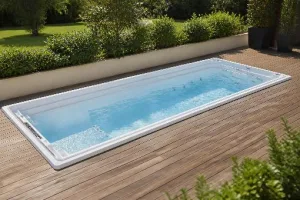
A 19-foot swim spa sits in an unusual middle ground. It is longer than almost any traditional hot tub on the market, yet it takes up far less space and costs considerably less to install than a lap pool. For homeowners weighing swim training against square footage, and for boutique wellness operators trying to fit […]
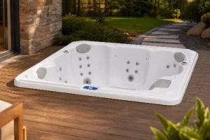
Why Size Changes Everything in a Spa Purchase A big jacuzzi is not just a larger version of a small spa. It changes how water moves, how heat is retained, and how many jets actually reach a body sitting inside. Homeowners often assume bigger simply means more room, but the engineering underneath shifts too. Pumps […]
If you’re wondering whether you can wear a tampon in a hot tub, the short answer is yes, but there are a few things worth understanding first. Heat, water pressure, and soak time all interact with menstrual products in ways that aren’t always obvious. This matters whether you’re easing into your own backyard spa or […]
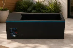
Cold water has been used for recovery long before it had a marketing name. Nordic villages built ice holes into frozen lakes, and Roman bathhouses reserved a cold room, the frigidarium, for the final stage of the ritual. The modern arctic cold plunge is that same idea, engineered into a compact tub that fits on […]
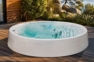
A 4 person round hot tub sits in a strange middle ground. It’s too small for a party of eight, but it’s also not a cramped two-seater squeezed onto a balcony. For couples, small families, or anyone with a compact patio, that middle ground is exactly the point. The round shape matters here too, since […]
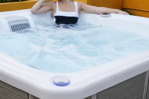
Buying a hot tub is the easy part. Getting permission to keep it in your backyard is where things get complicated for homeowners under a homeowners association. Yes, an HOA can deny a hot tub, and understanding why turns a frustrating rejection into a manageable approval process. Most HOAs don’t ban hot tubs outright. Instead, […]
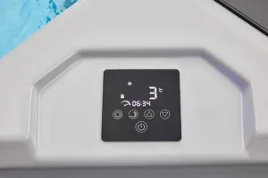
Cold plunging has become a fixture of recovery routines, but the question "can you cold plunge with Raynaud’s syndrome" stops a lot of people before they ever step in. Raynaud’s affects blood flow to the fingers and toes, and cold exposure is the exact trigger doctors warn about. That does not automatically mean cold plunging […]
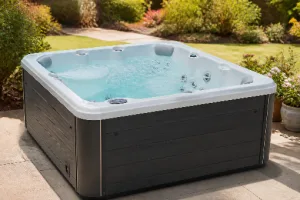
Why Seating Capacity Changes Everything A hot tub built for four people solves a specific problem: enough room for a couple or small family without the footprint and running costs of a larger spa. Shoppers looking for the best 4-person hot tub usually want something that fits a patio corner, won’t exceed a deck’s weight […]
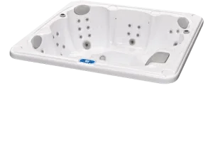
Gravel looks like an easy answer when you’re staring at a bare patch of yard and a delivery date. So the question comes up constantly: can you put a hot tub on gravel, or does that shortcut cost you a cracked shell six months later? The honest answer is that gravel can work, but only […]
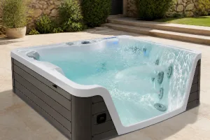
If you have ever caught a whiff of chlorine at the pool and wondered whether that same logic applies to your backyard spa, you are asking the right question. Are hot tub chemicals bad for you, or is that reaction more about misuse than the chemistry itself? The honest answer sits somewhere in between, and […]
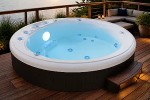
An acrylic hot tub is only as good as the details buyers skip past. Shell thickness, jet layout, and insulation quality decide whether a spa holds up through a decade of use or turns into a costly repair project. This guide breaks down what actually matters when shopping for a round acrylic hot tub, using […]
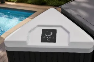
Why 50 Degrees Comes Up So Often in Cold Plunge Talk Anyone shopping for a cold plunge eventually runs into the number 50. It shows up in forums, product listings, and recovery blogs like a password everyone assumes you already know. In Fahrenheit, 50 degrees sits at the cooler end of what most physiologists consider […]
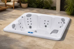
Anyone sharing a backyard spa with a curious dog has probably wondered: can dogs go in hot tubs safely, or is that water strictly a human-only zone? The short answer is that hot tubs are not designed for dogs, and letting one soak alongside you creates real risks for both the animal and the equipment. […]
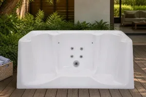
Shopping for the best affordable hot tub often starts with a simple frustration: most listings either skimp on real specs or bury you in marketing language. Buyers want warmth, working jets, and a shell that survives seasons outside. This guide breaks down what actually separates a budget hot tub from a poor one, using real […]
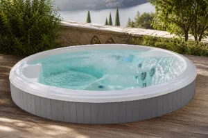
A backyard tub pool changes an evening’s rhythm. Instead of driving to a spa or waiting for a weekend getaway, you step outside and sink into warm water within minutes. The appeal is obvious, but choosing the right unit is less straightforward. Size, insulation, jet configuration, and water care systems all affect whether the tub […]
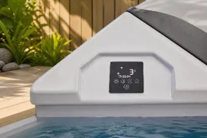
A 45 degree cold plunge usually refers to the camera angle used in product photography, not a tub tilted at that pitch. But the phrase has quietly become shorthand for something else too: the way people search for a clear, honest look at what a single-person cold plunge actually looks like before they buy one. […]
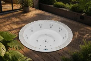
Shopping for the best garden hot tubs usually starts with a simple question: will this thing actually hold up outside, and will it feel good enough to use twice a week instead of twice a year? Those two concerns drive almost every decision that follows, from shell material to jet layout. This guide walks through […]
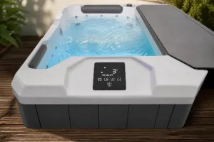
A gym owner in Colorado once told me he replaced his cold plunge twice in eighteen months. Not because members disliked it. Because the chiller couldn’t keep pace with back-to-back athlete sessions, and the acrylic shell cracked under freeze-thaw stress from an unheated storage room. Choosing the best commercial cold plunge isn’t about finding the […]
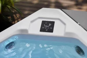
Stepping toward icy water triggers a very specific kind of dread. Cold plunge anxiety is common, and understanding why your body reacts this way is the first step toward a calmer, more consistent practice. Why Cold Water Triggers a Fear Response The moment skin meets cold water, the body activates its sympathetic nervous system. Heart […]

Pregnancy changes how your body handles heat, pressure, and buoyancy, so the question of whether pregnant women can go in hot tubs comes up for good reason. Warm water eases swollen ankles and tight lower backs, but a standard hot tub often runs hotter than what’s considered safe during pregnancy. Understanding the actual risk, and […]
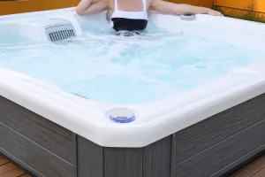
The Difference Between Bubbles and Real Hydrotherapy Anyone shopping for a spa eventually asks the same question: why do bubbles in hot tub water feel so different from a regular bath. The answer sits in engineering, not magic. Air alone creates a light fizzy texture, similar to a soft drink. Water jets, on the other […]
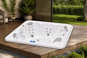
A 2 person hot tub solves a problem that larger spas create: not everyone has the yard, the budget, or the desire to heat a six-seat basin just to soak after work. Compact doesn’t have to mean cramped, though, and the right unit can deliver real hydrotherapy in a footprint that fits a patio corner […]
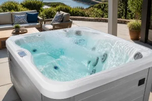
Anyone shopping for the biggest hot tub usually starts with one question: how many people actually need to fit inside without elbows knocking together. A crowded tub defeats the purpose of relaxing, and an oversized one can turn into wasted water and energy. Finding the right balance between seating capacity, jet performance, and running costs […]
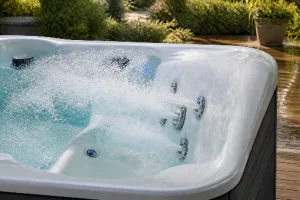
Shopping for the best hot tubs means sorting through jet counts, insulation claims, and seating layouts that all sound similar on paper. The real question is simpler: will this tub actually fit how you live, recover, and unwind. A six-person spa with dozens of jets solves a different problem than a compact two-seater tucked into […]
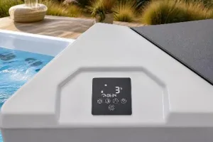
Anyone chasing the benefits of cold water immersion eventually hits the same wall: buying ice by the bag gets old fast. Searching for a cold plunge alternative usually starts here, at the intersection of convenience and cost, and it points toward equipment that keeps water cold without the daily hassle. The good news is that […]
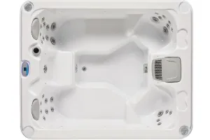
Standing over a cloudy hot tub with a bottle of household bleach in hand is a familiar moment for a lot of owners. The water looks off, there’s a faint smell you don’t trust, and bleach is sitting right there under the sink. So can you use bleach to clean a hot tub safely? The […]
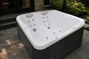
A 2 person corner hot tub solves a specific problem: you want the ritual of hydrotherapy without giving up half your patio to do it. Corner-friendly, compact outdoor spa designs have become the default choice for couples working with tight backyards, rooftop decks, or rental properties where every square foot counts. That demand didn’t appear […]
Shopping for the best outdoor hot tubs means balancing comfort, durability, and running costs against how you actually plan to use the tub. A weekend soak with friends demands different features than nightly therapy for sore shoulders after training. This guide breaks down the technical details that separate a decent spa from one that holds […]
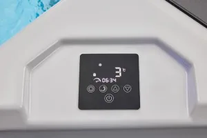
A cedar cold plunge has a certain appeal that’s hard to argue with. The wood grain, the earthy smell, the way it looks like it belongs next to a sauna rather than a swimming pool. For a lot of people searching for a cold plunge, cedar is the first material that comes to mind because […]
If you’re wondering "can i put an inflatable hot tub on my deck," you’re likely weighing cost against convenience. Inflatable models are cheap and easy to find, but decks introduce weight, moisture, and structural questions that many buyers overlook until it’s too late. This guide walks through what actually matters before you fill one with […]
小户外空间选购单人按摩浴缸指南:解析尺寸、喷嘴布局、保温与水质维护要点,帮助买家在预算与体验间做出合理选择。
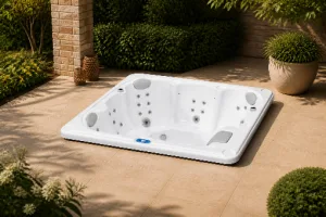
本文解析7人浴缸尺寸背后的容易被误导之处,涵盖占地面积、注水重量、安装间隙、喷头数量与保温设计,帮助买家理性判断实际舒适度。
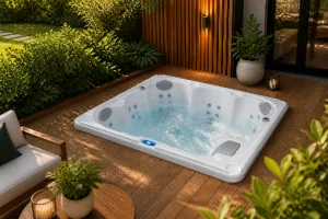
选购六人户外浴缸需综合考量座位设计、喷头布局、保温加热及水质维护,而非只看容量数字,才能确保长期实用与耐用。
50度冷水浴是恢复训练的理想温度区间,文章分析其生理效果,并介绍OF-CP01一体式制冷浴缸如何通过保温、过滤和恒温系统解决传统冰浴的不稳定问题。
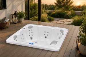
6人浴缸选购需综合水量、泵功率、喷嘴分布、过滤系统与隔热配置,以OF-6002 Pro为例说明如何按实际使用场景匹配规格。
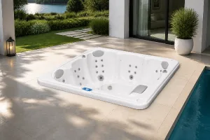
OF-2001两人温泉浴缸解析110V与220V电压差异,凭紧凑设计、22个按摩喷头、隔热层与臭氧过滤,适合公寓、露台等免电工安装场景。
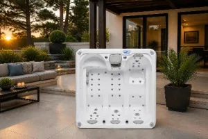
六人浴缸的价格差异主要取决于泵和加热器功率、喷嘴配置、外壳保温材料及过滤系统,这些结构性因素共同决定长期使用成本与体验,而非单看标价高低。
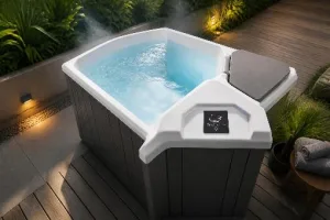
55度冷水浸泡兼顾疗效与安全,关键在于设备能否稳定控温;文章解析其生理作用、选购要点及OF-CP01等冷水浴缸的设计考量。
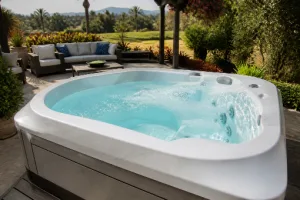
4座按摩浴缸价格差异主要由喷嘴配置、泵功率、隔热材料和过滤系统决定,而非座位数,选购时应综合比较这些配置而非只看价格。
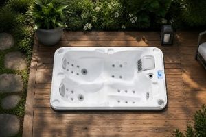
四人浴缸价格差异大,主要取决于外壳材质、喷头数量、泵功率、保温性能及电控配置,选购应结合实际使用需求综合评估性价比。
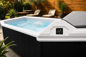
5分钟冷水浸泡的生理机制、温度控制的重要性、常见误区及冷水浴与专业冷浸缸的差异,助力养成持久有效的冷疗习惯。
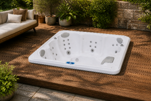
5人浴缸兼顾家庭与社交需求,需综合考量座位设计、喷嘴布局、能耗保温及水质维护,以OF-4001为例说明选购要点。
30英尺泳池SPA兼具训练与康复功能,通过对流系统、多级过滤和智能控制满足全年户外使用需求,选购前需综合考量场地、电力及使用目标。
40度冷水浸泡在耐受与效果间取得平衡,配备专用冷水机、数显控制、臭氧过滤和保温设计的单人浴缸,可解决冰浴温度不稳、维护繁琐等问题,让恒温冷疗成为可持续的日常习惯。
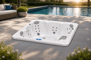
3人小型按摩浴缸适合空间有限的庭院或阳台,兼具喷嘴布局、保温、水质净化与氛围灯效等设计,以OF-3001为例说明如何按需选购。

单人浴缸看似省空间,但需求常随时间变化。文章对比单人与OF-V3004五人圆形按摩浴缸,从保温、水疗喷头、过滤系统等方面说明为何稍大尺寸更耐用实用。
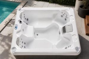
5人按摩浴缸兼顾家庭聚会与阳台空间,需综合考量喷嘴布局、功率、保温、水质净化及照明等因素后再决定购买。
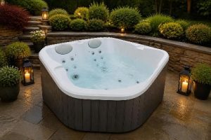
小尺寸2人户外泡浴缸兼顾空间与功能,配备22个按摩喷头、保温层、臭氧净化及氛围灯光,适合阳台、屋顶及小院使用。
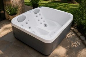
小型双人户外按摩浴缸兼顾水疗效果与空间限制,本文从喷头布局、外壳材质、保温层到灯光音响,解析选购要点及适用场景。
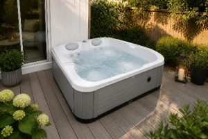
OF-2001双人按摩浴缸专为小空间设计,兼具定向水疗、多层保温、臭氧净水等功能,适合日常个人使用而非聚会场景。
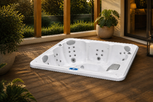
“15人热水浴缸”搜索背后其实是场地和聚会需求,但过大浴缸会稀释水疗效果并增加能耗,精心设计的4人浴缸(如OF-6006 Pro)往往更实用。
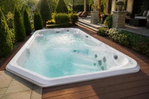
14英尺泳池SPA兼具游泳训练与水疗功能,选购需关注泵功率、过滤系统、按摩喷头布局及用电需求,而非仅比较品牌与外观。
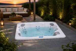
120V热水浴缸插标准插座即可使用,免电工免许可但加热较慢;240V硬接线系统功率更高,加热快、支持更多喷头,适合日常重度使用家庭。
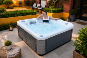
120伏热水浴缸可直接接入标准家用插座,无需240伏专用线路或电工改造,特别适合租户、公寓业主及小型空间。以OF-2001为例,配备22个喷嘴、臭氧净化系统和多层保温设计,在紧凑双人布局中实现集中水疗效果。虽然加热速度较慢,但通过优化绝缘和喷嘴密度,在降低安装成本的同时保持实用性能,更契合实际使用场景而非单纯追求规格参数。
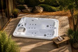
110V热水浴缸无需专线电路,插电即用,兼顾便利与性能,适合小型住宅、露台及出租房,重点在保温、水泵与喷头设计。
100加仑饲料槽可作冷水浴但缺乏保温、喷射与过滤系统,若追求恒温水疗、按摩或社交泡浴,专业热水浴缸如OF-V3004更具优势。
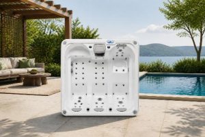
搜索”10人水疗浴缸”的买家通常追求容纳人数,但标称容量与实际舒适度存在巨大差距。大型浴缸水量、加热、维护成本高,而多数家庭实际使用仅2-4人。像OF-6006 Pro这样的4人浴缸配备59个喷嘴、双泵系统和优质绝缘,在喷嘴密度、按摩质量和运行成本上往往优于稀疏布局的10人浴缸,更符合真实使用场景。
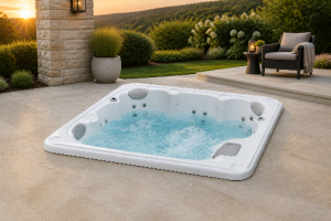
选购单人户外按摩浴缸时,外壳材质、隔热层、射流布局与过滤系统才是决定舒适度的关键,而非座位数量或喷嘴总数。
本文讲解10分钟冷水浸浴的生理反应、时长与温度关系,并介绍如何通过专业冷水浴缸设备实现更稳定、安全、可持续的冷疗恢复routine。
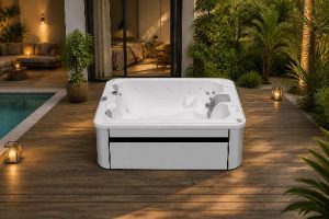
本文详解4人户外按摩浴缸的选购要点,涵盖尺寸、喷嘴布局、保温性能、水质净化及照明配置,帮助买家理性对比规格并合理安置使用。
While the evolution of aquatic therapy has driven a critical shift from basic, turbulent jets to Precision High-Flow River Currents, delivering a smooth, flat, and continuous swimming experience is only half of the equation. To safely contain and sustain the massive volume of water required for advanced swim lanes, the physical vessel must be engineered […]

When investing in a premium swim spa, modern homeowners, commercial developers, and distributors look for two essential factors: uncompromising aquatic performance and the flexibility to customize the spa to exact specifications. Legacy swim spas often fail to deliver on both, offering fixed, rigid layouts and choppy water currents that create unpleasant splashing. The Ocean Future […]
For decades, outdoor living design focused almost entirely on traditional, static features—a quiet patio, decorative landscaping, or a simple swimming pool. But in today’s fast-paced, health-conscious landscape, the modern luxury real estate market has reached a clear inflection point. Homeowners no longer want a backyard that just looks good—they want an active environment that restores […]
For decades, the standard blueprint for high-end residential luxury was defined by a massive, in-ground concrete swimming pool. It was a visual statement piece, but one that came with severe operational liabilities: massive spatial consumption, exorbitant year-round heating costs, complex civil engineering, and months of winter downtime. As we move through 2026, the global luxury […]

The global elite’s resistance to harsh chemical pool treatments like chlorine has officially reached its peak. Modern high-performers refuse to compromise their biological integrity, gut microbiomes, or skin barriers just to keep their pool water clear. The industry solution dominating discussions this week is the integration of Nanobubble Technology paired with Advanced Hydro-Filtration. [ Traditional […]
Historically, the premium wellness market operated on a simple premise: if you wanted to detoxify and optimize your health, you bought a traditional wooden sauna box for your home. You turned up the temperature, sat inside, and assumed the sweating process was doing its job. But as we advance through 2026, the elite wellness consumer […]

As we move further into 2026, the definition of luxury has undergone a radical transformation. High-net-worth individuals and forward-thinking developers are no longer just asking, “Does this property look impressive?” They are asking, “How does this property optimize my health?” Welcome to the era of Home Bio-Hacking. Beyond the Gym: The Rise of the “Longevity […]
Meta Description: Dislike the strong chlorine smell and red eyes from traditional pools? Discover how Ocean Future Spas utilizes advanced saltwater electrolysis and multi-stage micron filtration to deliver “skin-friendly,” crystal-clear water for your family. Summer is in full swing, and across North America and Europe, families are looking for ways to beat the heat. However, […]
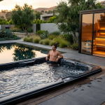
If you are a luxury property developer, landscape architect, or custom homebuilder operating in today’s market, you’ve likely noticed a radical shift in backyard design aesthetics. The traditional, bright “motel blue” chlorinated swimming pool is rapidly disappearing from high-end architectural blueprints. In its place, a new standard has emerged: deep charcoals, slate grays, and midnight […]

As summer heatwaves intensify, high-end property owners are investing in a complete summer heat acclimation sauna swim spa setup to build physical tolerance against extreme outdoor temperatures. While the instinctual response to rising humidity is to hide indoors under the air conditioning, the global longevity community is utilizing deliberate thermal conditioning to drop their baseline […]

If you have tried getting a quote for a traditional concrete pool installation recently, you already know the backyard renovation market has hit a point of breaking. Between soaring contractor labor rates, municipal permit delays that drag on for eight months, and local water restriction orders in several regions, digging a massive hole in the […]
Let’s be completely honest. When it’s the middle of July, and the outdoor humidity makes the air feel like warm soup, the last thing on your mind is crawling into a hot box to sweat. For decades, there’s been a common myth that home saunas are strictly a winter luxury—something you only turn on when […]

Let’s be real for a second. We’ve all envisioned the perfect summer: a sparkling blue pool in the backyard, kids splashing around, and you lounging pool-side with a cold drink. It’s the ultimate dream, right? But as anyone who has actually gone through the process of building an old-school concrete pool will tell you… the […]
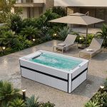
ummer temperatures are climbing across Europe and North America. Landscape architects and premium homeowners now face a shared challenge. This challenge is Eco-Anxiety. Prolonged heatwaves are triggering strict water restrictions across many regions. Therefore, many people need a sustainable luxury pool alternative. They want to keep their summer lifestyle intact. However, they must avoid draining […]
Imagine lacing up your running shoes at 7 a.m. and already feeling sweat bead down your back. By 8 a.m., you’re drenched, exhausted, and ready to call it quits. Or worse—you drag yourself to the gym, only to fight for a machine in a stuffy, overcrowded room where the air smells like stale sweat. This […]
Integrating a daily sweat session is a foundational longevity practice for modern biohackers and athletes looking to accelerate muscle recovery. However, as home units become more popular, a critical safety question arises: are infrared saunas safe for daily use? The answer is yes—but only if the cabin environment is chemically pure. When operating a compact […]

In today’s fast-paced world, carving out time for self-care shouldn’t require a trip to a crowded spa or a dedicated room in your home. For anyone who’s dreamed of having a sauna but thought they didn’t have the space—or hated sharing a steamy room with strangers—small single-person saunas are the game-changing solution. They combine all […]
An infrared sauna room is one of the most popular options because it delivers gentle, targeted heat without the extreme temperatures of traditional saunas. Instead of warming the air, infrared panels warm your body directly, which many people find more comfortable and easier to tolerate. Regular sessions may support relaxation, stress reduction, and muscle recovery. […]
In the pursuit of peak human performance, the sauna has evolved from a traditional luxury into a critical tool for metabolic health. However, the efficacy of heat therapy is entirely dependent on the integrity of the environment. At Ocean Future, the OFS-04 Series represents our most advanced engineering response to the demands of modern longevity […]
Looking for a private home sauna but worried you don’t have enough space? The OFS06A-1 single-person sauna is exactly what you need. No need for a big backyard, no need to remodel your house. This compact sauna fits perfectly in bathroom corners, spare rooms, home gyms, apartment nooks, even your bedroom side space. We built […]

In the chaos of modern life, genuine relaxation and consistent wellness care often feel out of reach. Public spas come with crowded spaces, inflexible hours, and awkward small talk, while traditional saunas often deliver stifling, overly hot air that leaves you feeling drained instead of refreshed. What if you could bring professional-grade thermal therapy home, […]
Before buying an infrared sauna, the top question for 90% of consumers is: “Is it really safe?” Unlike traditional steam saunas, infrared saunas use far-infrared radiation to heat the body directly, which leads to many safety concerns. This guide, based on research from the FDA, Mayo Clinic, and Harvard Health, answers all your safety questions […]

In the world of high-end wellness, we often hear the term “Duru”—a Turkish word signifying purity, clarity, and a state of being untouched. Achieving this “Duru” state in our chaotic, modern lives requires more than just a quick shower. It requires a systemic intervention. At the intersection of ancient recovery traditions and modern engineering lies […]

In the fast-paced world of modern wellness, few practices have stood the test of time as effectively as heat therapy. While once considered a luxury reserved for high-end spas, the modern sauna room has evolved into a sophisticated health tool. Today, it sits at the intersection of ancient tradition and cutting-edge physiology, offering a dual-action […]
When most people think of a hot tub, they picture a weekend of relaxation or a social centerpiece for a party. But for those of us in the manufacturing industry, we see a hot tub as a sophisticated piece of hydrotherapy equipment. So, are hot tubs actually good for you? The short answer is a […]
At-home heat therapy is booming. But with so many products flooding the market, it’s easy to be misled by overstated marketing claims. Let’s cut through the hype. Here is the factual, engineering-level breakdown between portable sauna blankets and true traditional home saunas—so you can make an informed investment in your health. Quick Product Overview Infrared […]
The short answer is yes, infrared saunas are safe, but the real risks are invisible and often ignored by retail brands. As a manufacturer, we look past the “light” and focus on the two critical factors that determine if your sauna is a health sanctuary or a chemical hazard: Air Quality and EMF Shielding. The […]

Walk into any luxury gym or wellness center, and you’ll hear the claim: “Burn 500 calories just by sitting in the sauna.” It sounds like the ultimate “biohack” for weight loss. But as a manufacturer focused on engineering and biological safety, we believe in giving you the unfiltered truth. Can a sauna help you lose […]
For many wellness enthusiasts, the dream of a home sauna is often crushed by two words: “The Lease.” Standard high-heat saunas usually require permanent installations, 240V electrical upgrades, and a heavy footprint that simply doesn’t work for a rental property. On the other end of the spectrum, the market is flooded with low-cost “sauna tents” […]

In 2026, the global conversation around health has shifted from “treating illness” to “optimizing longevity.” We are no longer just looking to live longer; we are looking to live better. This is the essence of Preventive Wellness, and at the heart of this movement is a centuries-old practice backed by modern science: the sauna. 1. […]
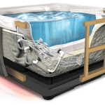
Discover the OF-6004, a 6-person luxury spa. This detailed review goes beyond the marketing fluff to expose the engineering secrets—including Lucite®/Aristech® multi-layer acrylic, targeted 316 stainless steel jets, high-efficiency insulation, and certified Balboa® controls. Plus, see a real installation spotlight from the online spa community! 1. Beyond the Surface: What Real Spa Owners Actually Care […]

Looking for a safe far-infrared sauna? Most “Low EMF” marketing ignores ELF (Extremely Low Frequency) and toxic glue off-gassing. To ensure safety and performance, prioritize combined EMF/ELF shielding, solid Tongue and Groove construction (no glues), and certified control systems (ETL/CE). 1. The Invisible Risk: EMF vs. ELF Shielding Most consumers search for “Low EMF saunas,” […]
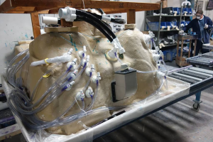
Part I: The Hidden Traps – Why Cheap Hot Tubs Cost More Over Time When most first-time buyers evaluate a professional-grade hot tub, they are often captivated by aesthetic features like cascading waterfalls or Bluetooth speakers. However, from the perspective of a sanitary ware R&D professional, these are merely surface-level distractions. The true value of […]
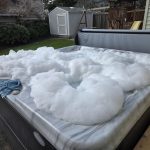
Part 1: Why Does Excessive Foam Appear After a Fresh Water Change? 1. The Hidden Culprit: Biofilm Even if you regularly use Bromine or other sanitizers, they only kill free-floating bacteria in the water. They struggle to penetrate Biofilm—a stubborn, protective layer that clings to the inside of your plumbing, shielding colonies of bacteria and […]
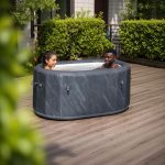
“We recently saw a common question on Reddit from a user in Florida wondering if they should cycle their cold plunge chiller between 50°F and 60°F to save energy. At Ocean Future, our engineering team has a different take: Stability is king.” Part 1: The Common Cold Plunge Chiller Question, Answered The short answer? Don’t […]

If you’re planning a DIY backyard wood stove sauna, you’ve probably run into the two most popular build options: thick T&G (Tongue & Groove) no-insulation walls, and framed insulated sauna walls. Which one fits your needs? We’re breaking down the real-world pros, cons, and tradeoffs to help you pick. Thick T&G (No Insulation) Sauna: The […]
We often say that the best relaxation sessions aren’t just about the water—they’re about the atmosphere you create. Imagine the perfect evening: a curated playlist on the speakers, a chilled drink in hand, and the steam rising into the night air. It’s an experience that should be savored, not rushed. However, the ultimate “mood killer” […]
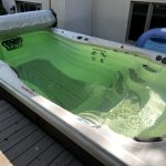
The Frustration: You’ve dumped gallons of liquid chlorine and bags of shock into your pool, yet the water remains a stubborn, cloudy green. It feels like a losing battle against nature. But the problem isn’t the amount of chemicals—it’s the Chemistry. The Culprit: Cyanuric Acid (CYA) Overload Most pool owners use stabilized chlorine tablets (trichlor). […]

OFS01-3 infrared sauna delivers deep relaxation, improved circulation, and modern home wellness.
OFS01-3 far-infrared sauna delivers premium home wellness, relaxation, and detox benefits.
OFS01-3 infrared sauna room offers ultimate relaxation, detox, and wellness at home.
OFS01-1 infrared sauna delivers advanced health, relaxation, and detox benefits for home use.
Transform your wellness routine with the OFS01-1 infrared sauna for relaxation and detox.
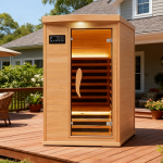
Experience the OFS01-1 infrared sauna for relaxation, detox, and enhanced home wellness.
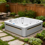
Discover the OF-120AT swim spa for fitness, hydrotherapy, and year-round home wellness.
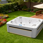
OF-120AT swim spa delivers training, hydro-massage, smart entertainment, and energy-efficient relaxation.
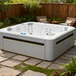
OF-120AT swim spa delivers exercise, hydro-massage, and energy-efficient relaxation for the whole family.
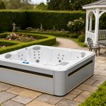
OF-120T swim spa delivers compact fitness, hydrotherapy, and family relaxation at home.
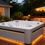
OF-120T swim spa delivers fitness, hydrotherapy, and luxury in one compact design.
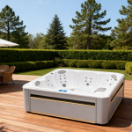
OF-120T swim spa combines elite fitness training with luxury hydrotherapy relaxation.
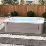
Shop the OF-3001 Pro hot tub for luxury, efficiency, and ultimate outdoor relaxation.
Discover the OF-2001 Pro hot tub, blending smart relaxation with premium spa comfort.
Explore why the OF-3001 Pro hot tub leads in performance, design, and relaxation.
Discover the OF-2001 Pro hot tub with premium comfort, relaxation, and hydrotherapy.
Experience the OF-R001 patio hot tub with hydrotherapy, energy efficiency, and entertainment.
Discover the OF-R001 hot tub with 38 jets, insulation, and Bluetooth entertainment.
Discover the OF-R002 hot tub with hydrotherapy, energy efficiency, and family-friendly design.
Experience the OF-R002 hot tub with reliable heating, strong jets, and family-friendly design.
Soaking in a hot tub, enveloped in steam amid the gentle bubbling of water, connotes leisure and escape.
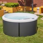
Hot tubs combine human-centric design and environmental responsibility.

These hot tubs, silently lined up will in the future becomeA vessel of happiness for many families:Some people wash away their fatigue here.Children play and grow up here.Couples share their mornings and evenings here…And right now, we’re putting the finishing touches on these stories.
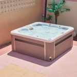
The hot tub relaxes the body with heat, thereby drawing away the accumulated fatigue and stress from the day. It also creates ideal conditions to slip into a deeper sleep by increasing blood flow and regulating temperature. Scientific studies have proven that hot baths can bring a very good improvement in sleep quality, thus making […]
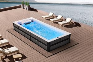
When choosing between a swim spa and a hot tub, consider your wellness goals, lifestyle, and personal preferences. Although both options promote relaxation and reduce stress, they serve different purposes and have distinct features. Understanding the differences between a swim spa and a hot tub will help you choose the best option for your needs. […]
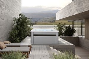
An excellent addition to your home is an outdoor spa tub, which offers you a tranquil haven where you can unwind, revitalize, and spend time with your family and friends. However, routine care is necessary to keep the bathtub clean, functioning, and attractive. Maintaining the best possible condition for your outdoor spa tub not only […]
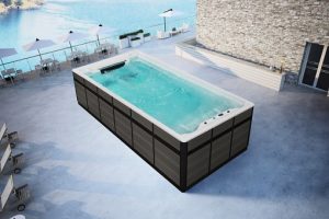
Swim spas are a modern addition to many homes, combining fitness, relaxation, and fun in one. These versatile water systems have gained widespread popularity over the years because they combine what swimming pools and hot tubs offer individually into one compact unit. Whether you are an athlete looking to improve performance, someone seeking stress relief, […]
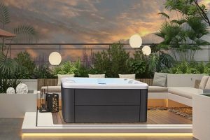
Hot tubs have evolved significantly over the years. From simple relaxation equipment to design innovations, technology has transformed them into luxury products with therapeutic benefits. Modern hot tubs are designed for comfort and relaxation, featuring advanced technology for users. This passage explores the evolution of hot tub design and the technological innovations that have redefined […]
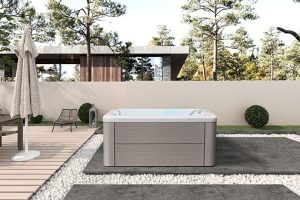
Investing in an outdoor spa is a great way to enhance your lifestyle, offering a tranquil retreat where you can relax, unwind, and rejuvenate. Whether you want to create a luxurious backyard oasis or simply enjoy a soothing soak after a long day, the right outdoor spa can make quite a difference. With so many […]
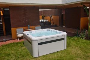
In today’s fast-paced world, where stress is an inevitable part of everyday life, finding ways to relax and rejuvenate is essential to maintaining a healthy body and mind. One of the most effective and luxurious ways to relax is to enjoy the soothing comfort of a spa bath. Whether looking to relieve stress, soothe sore […]
We are very pleased to share that Ocean Future is actively participating in the Piscine Global Expo 2024, which is being held at the Versailles Exhibition Center in France from November 19th to 22rd, 2024. Our booth, located in 6F132, is currently experiencing a steady stream of visitors, and we have already felt the tremendous […]

Experience The Superior Quality And Design Of Modern Hot Tubs And Innovative Swim Spas At Piscine Global Expo 2024 The much-anticipated Piscine Global Expo will be opening in France and we will be exhibiting at it. The world’s most important bathtub exhibition will be the perfect stage to present our products to you. From 19th […]
Please Join Us On INTERNATIONAL POOL SPA PATIO EXPO 2024 Exhibition The INTERNATIONAL POOL SPA PATIO EXPO 2024 exhibition in UNITED STATES will be held on 12th-14th NOVEMBER, we will meet you there in Booth 8916. The customers are from all over the world. We are sincerely to invite you to come to visit us. […]

We are pleased to share the success of Ocean Future’s participation in the prestigious 28th Kitchen & Bath China 2024 exhibition, which took place from May 14th to 17th at the Shanghai New International Expo Centre. Our booth, located in Hall E6, Booth E12, attracted numerous visitors who were eager to explore our latest innovations in […]

The second phase of the 135th Canton Fair was successfully held from April 23 to 27, 2024. With the theme of “Quality Home Furnishing”, it concentrated on displaying 15 exhibition areas in three major sections: household products, gifts and decorations, and building materials and furniture. So Ocean Future seize this opportunity to bring our products […]

Ocean Future, the pioneering brand in wellness and relaxation solutions, has just unveiled its latest innovation in the realm of sauna experiences. Introducing the Ocean Future Infrared Sauna Rooms, a revolutionary addition to the world of home spas. Ocean Future Infrared Sauna Room has launched 11 new products this time, designed with the most advanced […]

This swim spa is equipped with an advanced swimming training system, which can provide users with a professional training experience. By adjusting the water flow speed, users can set the appropriate swimming intensity according to their needs and conduct efficient swimming exercises. In addition, the spa tub has multiple built-in massage jets, which can provide […]

This spa tub is equipped with 41 powerful jets, providing a deep hydrotherapy massage experience, relieving body fatigue, relaxing the mind and body, and providing you with unparalleled comfort. It is also equipped with Bluetooth function, allowing you to enjoy clear music and entertainment while relaxing, adding more fun. The design of OF-V3006 focuses on […]

This swim spa is equipped with a high-performance circulation filtration system, combined with advanced water flow regulation technology, to provide a uniform and stable water flow, suitable for swimming training, rehabilitation therapy, and relaxation. Multiple massage jets can accurately relax muscles, relieve fatigue, and bring immersive spa enjoyment. It uses a smart control panel to […]

OFS01-4 uses advanced far infrared heating technology, which can deeply penetrate the skin, promote blood circulation and relieve muscle fatigue. Compared with traditional saunas, infrared heating is more efficient and consumes less energy. At the same time, it can help the body excrete toxins, enhance immunity, and bring you a deeply relaxing treatment experience. This […]

Designed for family and friends, this hot tub can accommodate 5 people to enjoy hydrotherapy relaxation at the same time. Made of high-quality materials to ensure durability and stability, you can enjoy a comfortable bathing experience in any environment. Equipped with 59 high-performance massage jets, this outdoor spa tub provides strong and even water flow […]

OFS06C-5 combines traditional sauna and infrared technology to provide users with a more comprehensive physical therapy experience. Traditional sauna stoves can quickly heat the entire space, bringing a deep sweating pleasure, while the infrared heating system can directly act on the human body, penetrate deep into the skin, and promote blood circulation and metabolism. This […]

PRODUCTS

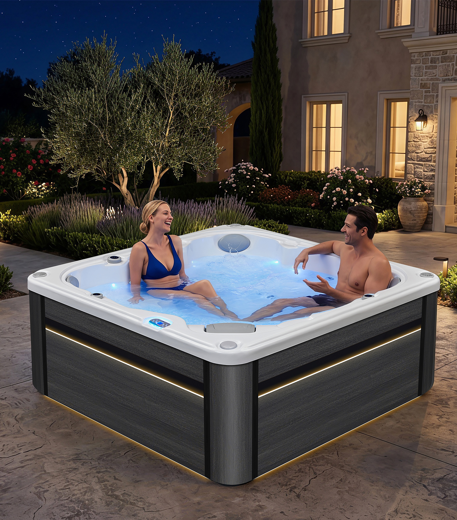
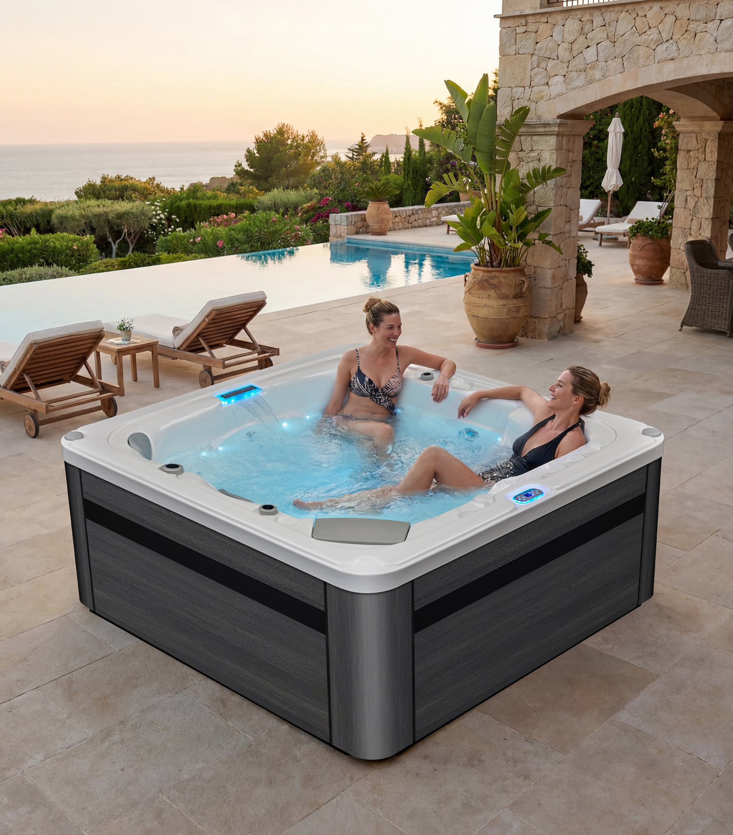
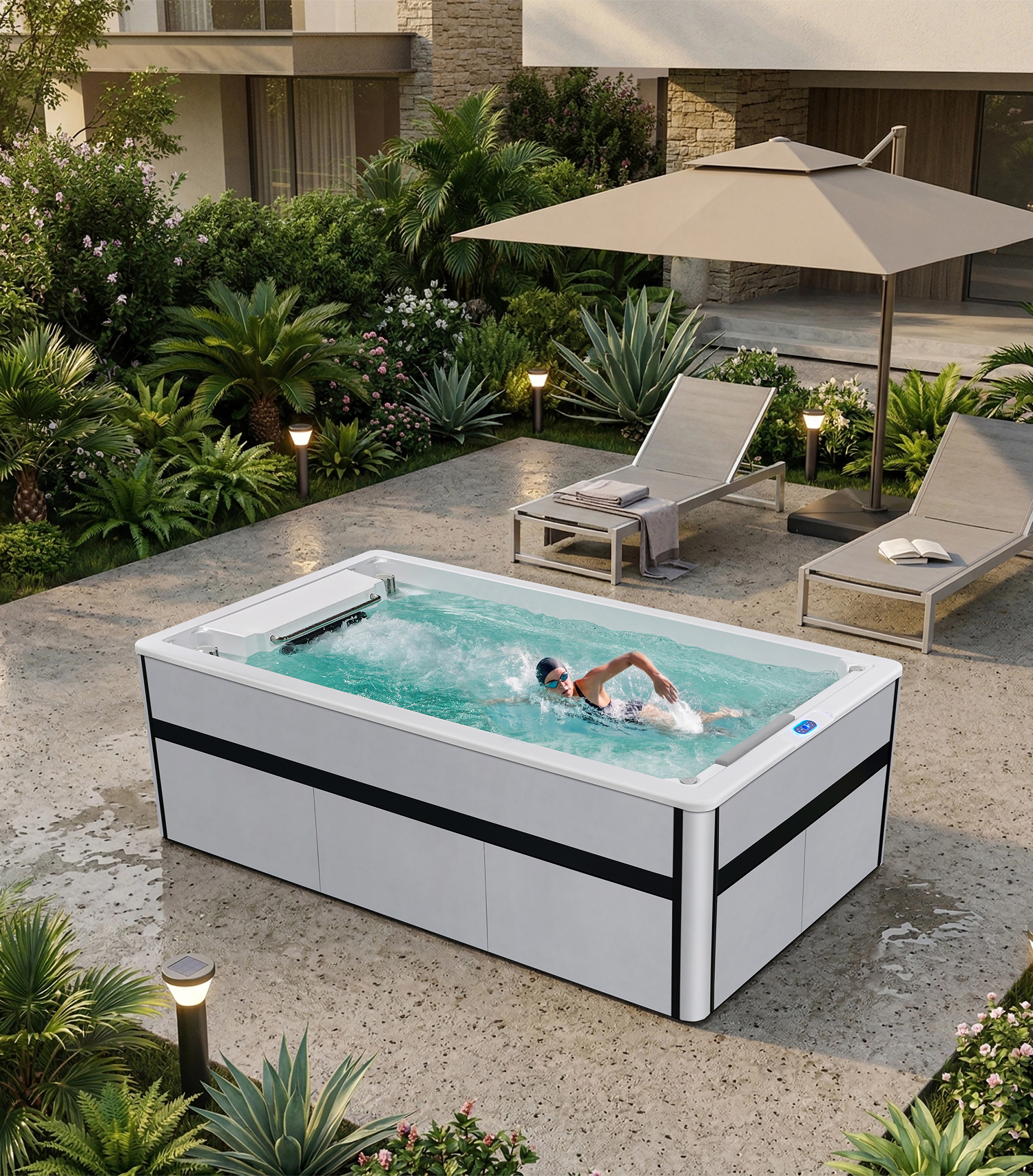
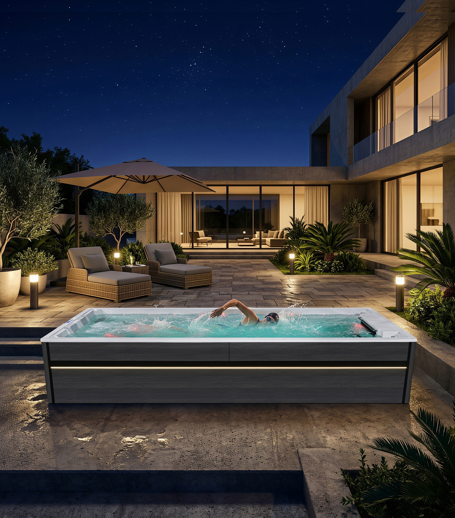
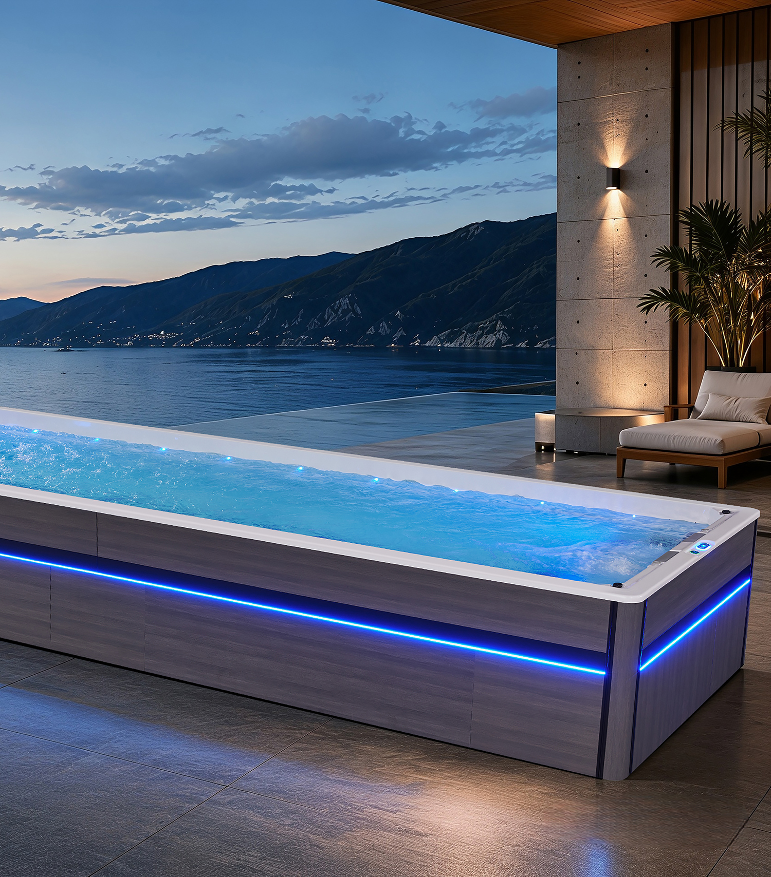
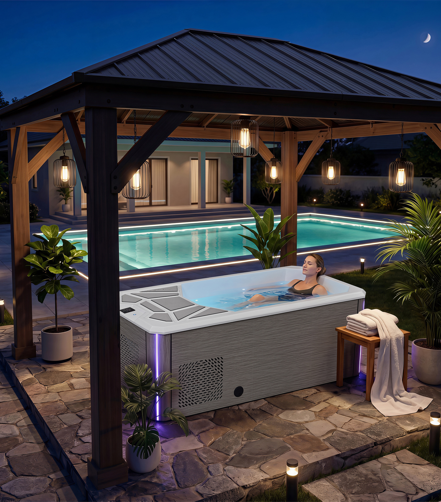
 3 Person
 5000*2200*1250mm